Wireframe Rendering in 3ds Max
How to present topology of your 3d models for a portfolio or CG gallery's. How to perform a wireframe rendering of 3D meshes in V-Ray or Mental Ray. How to adjust lighting of the scene and globally override all materials. You will also understand how to render 3D models with multiple subdivision iterations using an isoline rendering technique. Also, you will see a trick how to compositing two renders into one using 3ds Max only.
Contents
Who Needs a Wireframe Images
Hi everyone!
Most 3D Artists who have made great visualizations have probably shared them at least once, for example, in public 3D galleries, forums, social networks, etc., to get feedback and likes. If the model looks complicated, people in the comments section immediately ask to show the model grid to see how it is done. Moreover, according to the rules of some galleries, you even need to provide a wireframe of 3d scene as proof of authorship.
Many of those who want to learn from more experienced colleagues follow WIP (Work in Process) topics or manage them on numerous CG forums. Of course, they want to share the technical details of what they did, so they need to demonstrate the 3D grids of the 3D models they are working on.
Who among 3D artists would not want to have extra money selling their own models at 3D stocks, such as, for example, Turbosquid? You've probably noticed that in addition to strict technical information, such as the number of polygons and vertices, the presence of texture or materials, almost all great models not only have colorful renderings of textured model on all sides, but also necessarily accompanied by wireframe images. This not only attracts attention, but also directly helps the potential buyer to assess the quality of the 3d model itself.
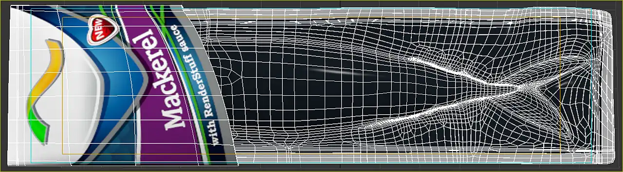
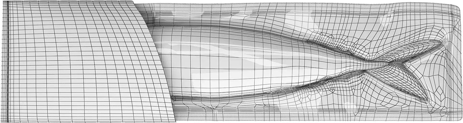
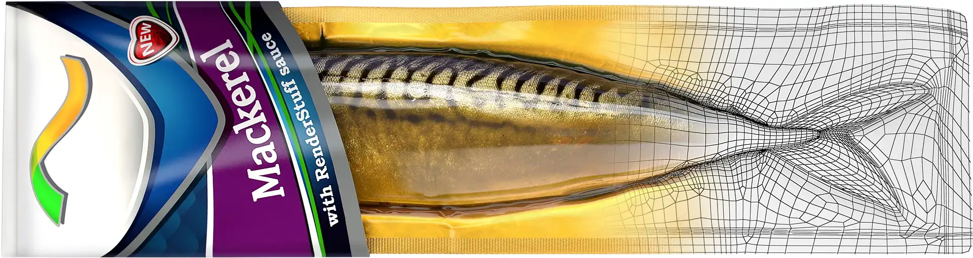
Probably the most interesting case, which always requires a demonstration of a wireframe, is when 3D visualization is photorealistic enough to ask the question: "Is this image a photo or a realistic 3D rendering?". This question is especially common when unusual items are visualized. Look at this image, for example:

Is this a photo of a real packaged mackerel or it is a 3D-rendered image?
The best answer to this question, to the enjoyment of curious well-wishers or for the frustration of annoying skeptics, is to show a wireframe of this 3D model from the same camera from which this realistic 3D visualization was made.
However, the 3d wireframe imagery should not be left as a prerogative for the CG community only. The wireframe images plays a key role in portfolio of any talented CG Artist, whose works can hardly be distinguished from real photography by the eye of the average viewer (customer or potential employer), who is neither a skillful 3d visualizer nor a 3d-modeling pro. After all, most end users of 3D visualization are not very familiar with 3D technology. Not every architect, designer or even engineer can easily notice specific details that distinguish 3D rendering from a regular photo. Therefore, they absolutely need to see a clear demonstration of the wireframe. Several wireframe images is the most compelling argument that the observed image is apparently a computer-generated image (CGI) they are looking for.
So how can we present meshes of our 3d models to have both, a great demonstration of its topology and at the same time have an images that is just interesting to look at?
The following tutorial is the answer that question.
Viewport Screenshot as a Basic Solution
The easiest way to make a wireframe image is simply to take a screenshot of the viewport with any screen capture software.
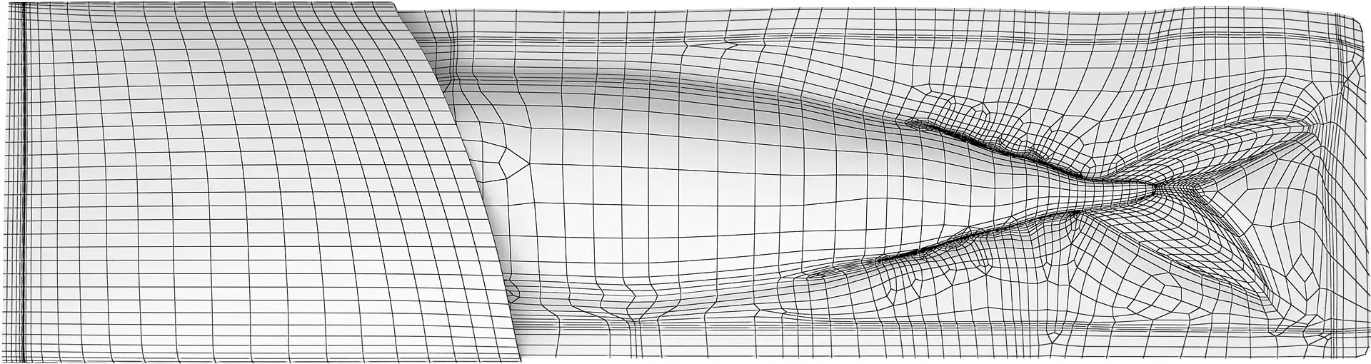
In case a demonstration of the scene grid is required to confirm the computer origin of the image, it is better to take a screenshot from literally the same camera from which the image to be confirmed was rendered.
The resulting image clearly proves that we have a 3D model and not a photo, but the appearance of the resulting image as a whole can hardly be called presentable in other aspects. Such an image, captured from the screen, looks dirty and is more likely to make the portfolio worse than increase its attractiveness to potential customers. Especially when it displays a Safe Frames and other viewport specific details.
It should be noted that 3ds max itself has a screen capture tool. It is in the menu Tools => Preview - Grab Viewport => Capture Still Image.... You can use it to take a viewport screenshots.
Wireframe Rendering in V-Ray: Theory
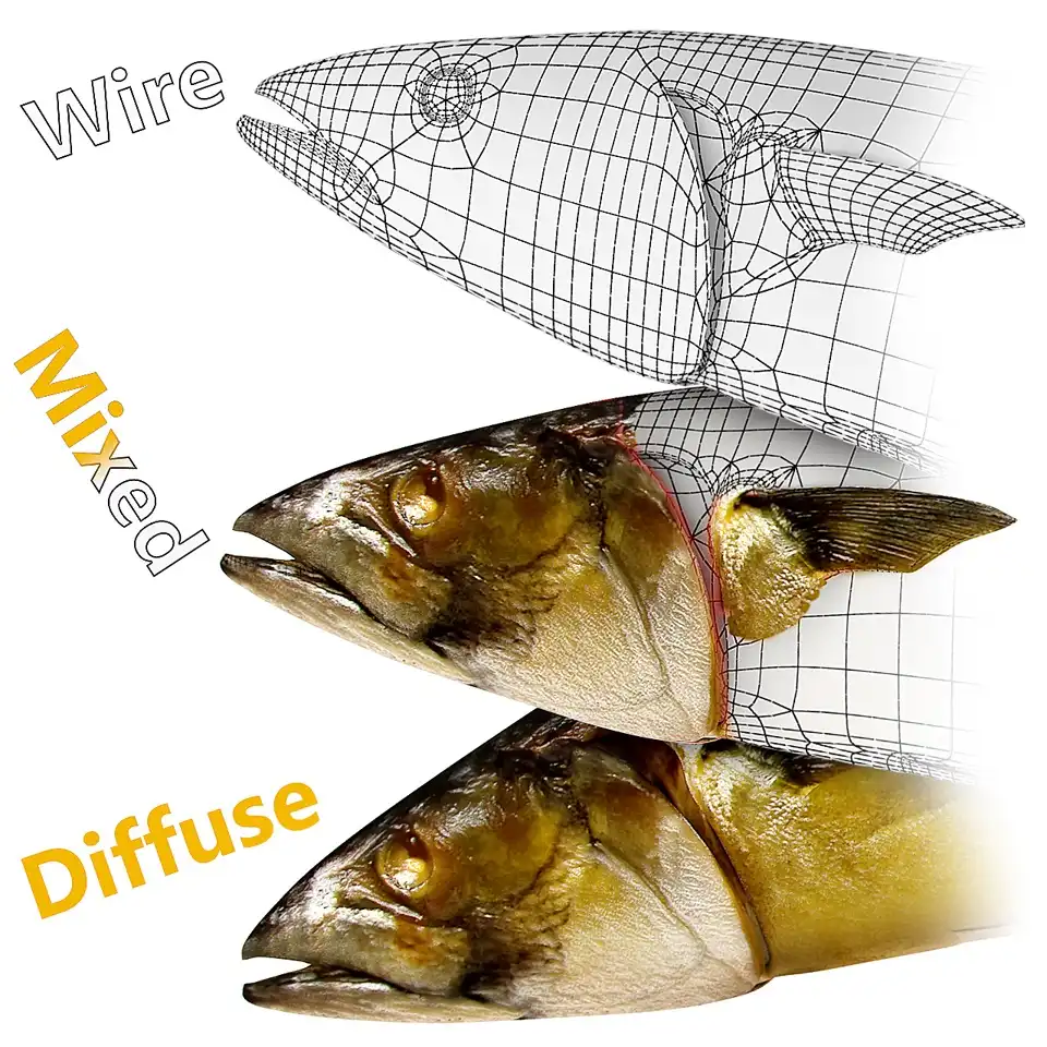
Quite another matter - a full-fledged three-dimensional visualization of a nice white model, with lighting, shading, covered with black contrasting lines showing the topology of the 3d-model. This is such an interesting and presentable method of demonstrating a 3d model mesh that it is sometimes more interesting to look at than the final photorealistic rendering of this model with all the applied textures and materials. Here you can see both the volume of the shape and the base-mesh topology.
To make such a rendering is quite simple. Most modern render engines have a special shader that allows you to visualize edges of 3d model as a texture.
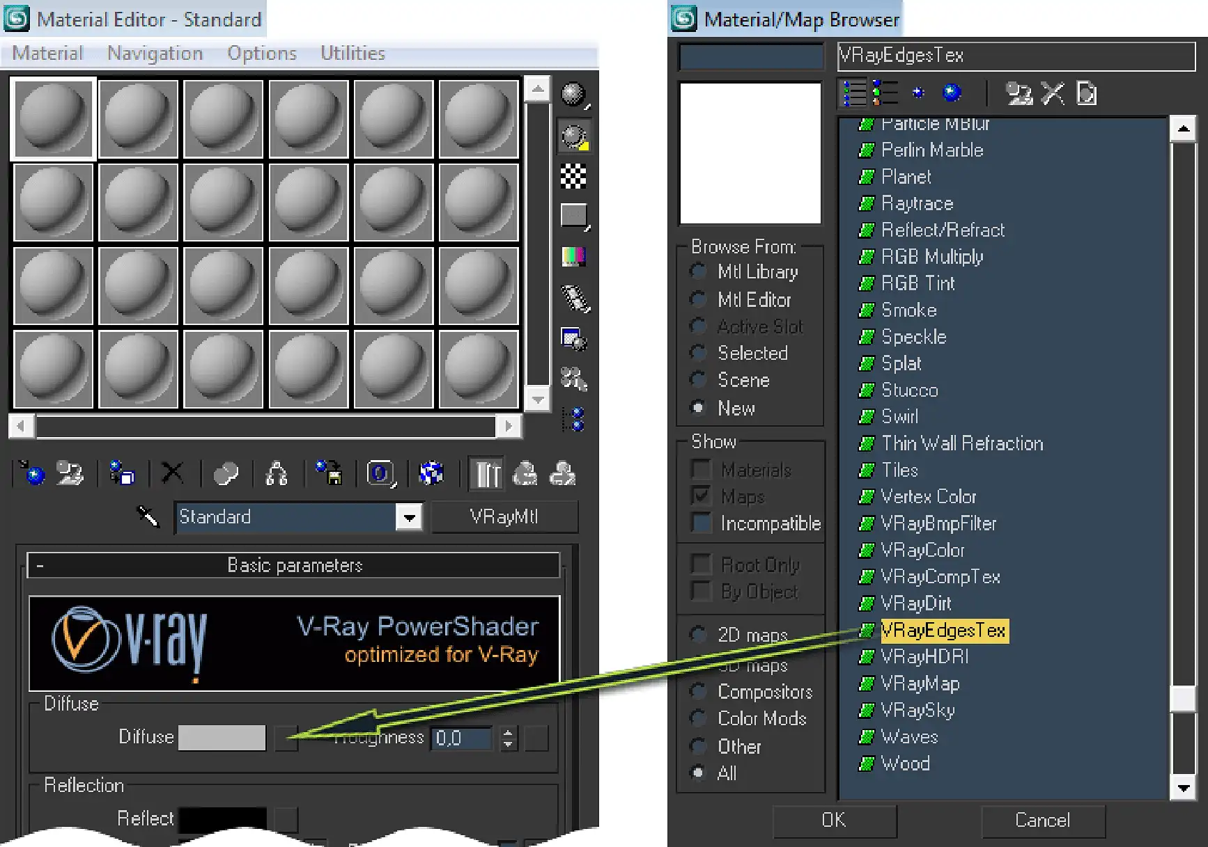
In V-Ray, this type of shader is represented by a specialized parametric texture map call VRayEdgesTex. It is a simple map that has only a few parameters to take care of.
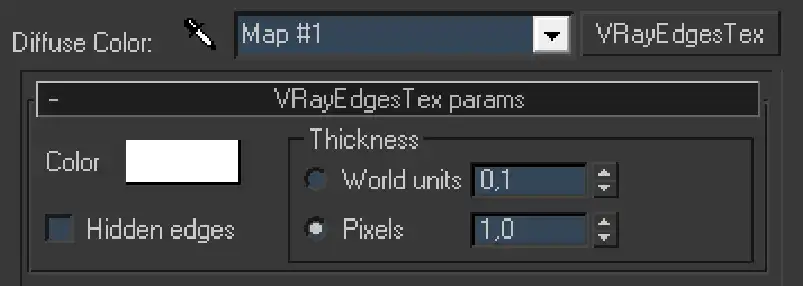
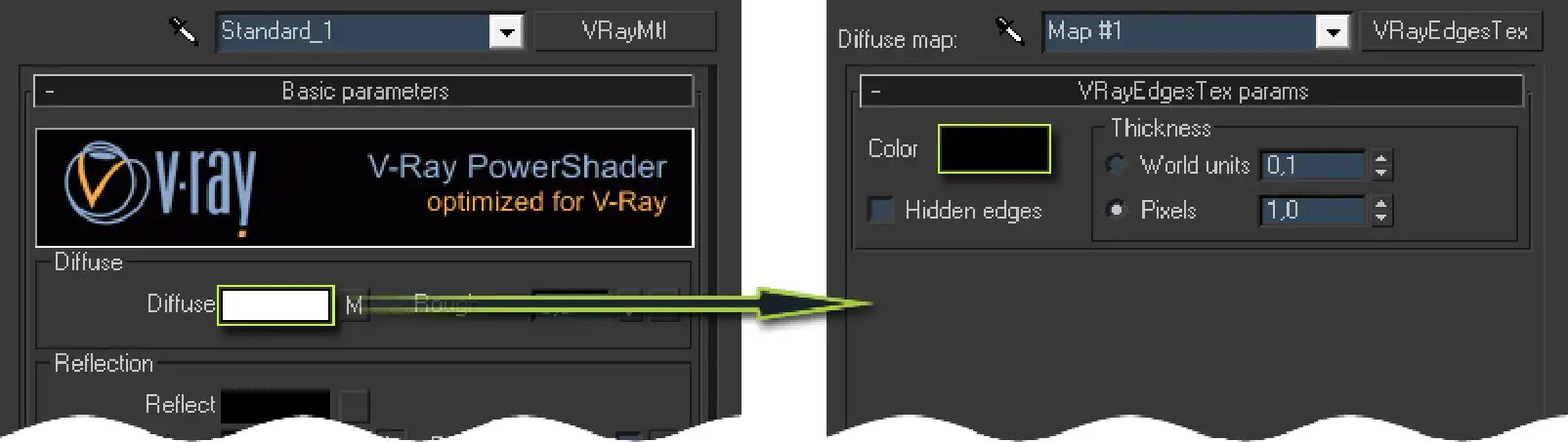
Color is a slot with a color sample. Defines the color of the rendered edges.
Note that VRayEdgesTex does not visible in the viewport, only during rendering.
Just click on the color field, which is white by default, and select a desired color in the color selector window that opens. Usually black, this is the most contrasting, and therefore the best color for topology lines. But whatever it is, it's a matter of taste.
Hidden edges option allows to render a hidden edges of the mesh.
The fact is that polygons are just a way to present sets of triangles, mainly for a more beautiful view in the viewport and the convenience of editing the mesh of 3d model. One quad polygon is actually a combination of two triangles, where the edge of their junction is hidden. Despite the fact that the object in the 3D editor is considered "polygonal", it is still technically assembled from triangles. Therefore, this function allows you to visualize a true triangular mesh topology.
There are two parameters in the Thickness zone that responsible for the thickness of the rendered edges.
World units option allows you to specify the thickness of the edges in units of the scene. Such as millimeters, centimeters, inches, etc., according to the units set in the main scene unit settings Customize => Units Setup....
Pixels allows you to set the thickness of the edges (topology lines) in pixels on the rendered image. How many pixels you set there, with that number of pixels, the topology lines will be represented, regardless of the final resolution.
When choosing pixels as a thickness measurement of edges, keep in mind that the thickness of the edges will be always equal to the specified number of pixels and does not decrease or increase as the distance of the edges to the camera increases or decreases. This means that the 3d model located close to the camera and the 3d model away from it will have the same edge thickness on the final render. This also means that distortion of the camera's perspective does not affect the thickness of the edges specified in pixels. This must be taken into account, then you choose which units to use.
Wireframe Rendering in V-Ray: Practice
To use the VRayEdgesTex map, you must first choose a base material, such as VRayMtl, and then put the VRayEdgesTex map in its Diffuse slot for the maps. Then, you need to set thickness and color of the edges in VRayEdgesTex map.
The VRayEdgesTex affects only the properties of the edge rendering and is applied on top of the of material's Diffuse color. This means that to specify the main filling color of the model (color of the polygons), you need to set a desired color in the Diffuse color slot of VRayMtl itself.
For example, if you want to have a white model with black edge lines (as in the examples of this tutorial), you need to set a Diffuse color of VRayMtl as white, then go down to VRayEdgesTex and set its color as black. It's a bit confusing, but look at the screenshot below and everything will be clear.
Wireframe Rendering in V-Ray: Tricks
Global Materials Override
Usually wireframe visualization is required for the whole scene. In this case, there is no need to apply wireframe material to each scene object. The V-Ray renderer has a feature of global redefinition of materials. This feature allows you to render a scene without changes in the material actually applied to the objects, but to get a final render of the scene as if other material had been applied to all objects in the scene. In other words, global material override option.
It located at: Render Scene (F10) dialog => V-Ray tab => V-Ray: Global switches rollout => Override mtl checkbox => Override mtl slot (none by default). Then you set Override mtl checkbox checked the Override Exclude... button become available.
To override all the scene materials at once during rendering, all you need to do is place the required material in the Override mtl slot. In our case, it will be a wireframe material that we have just created.
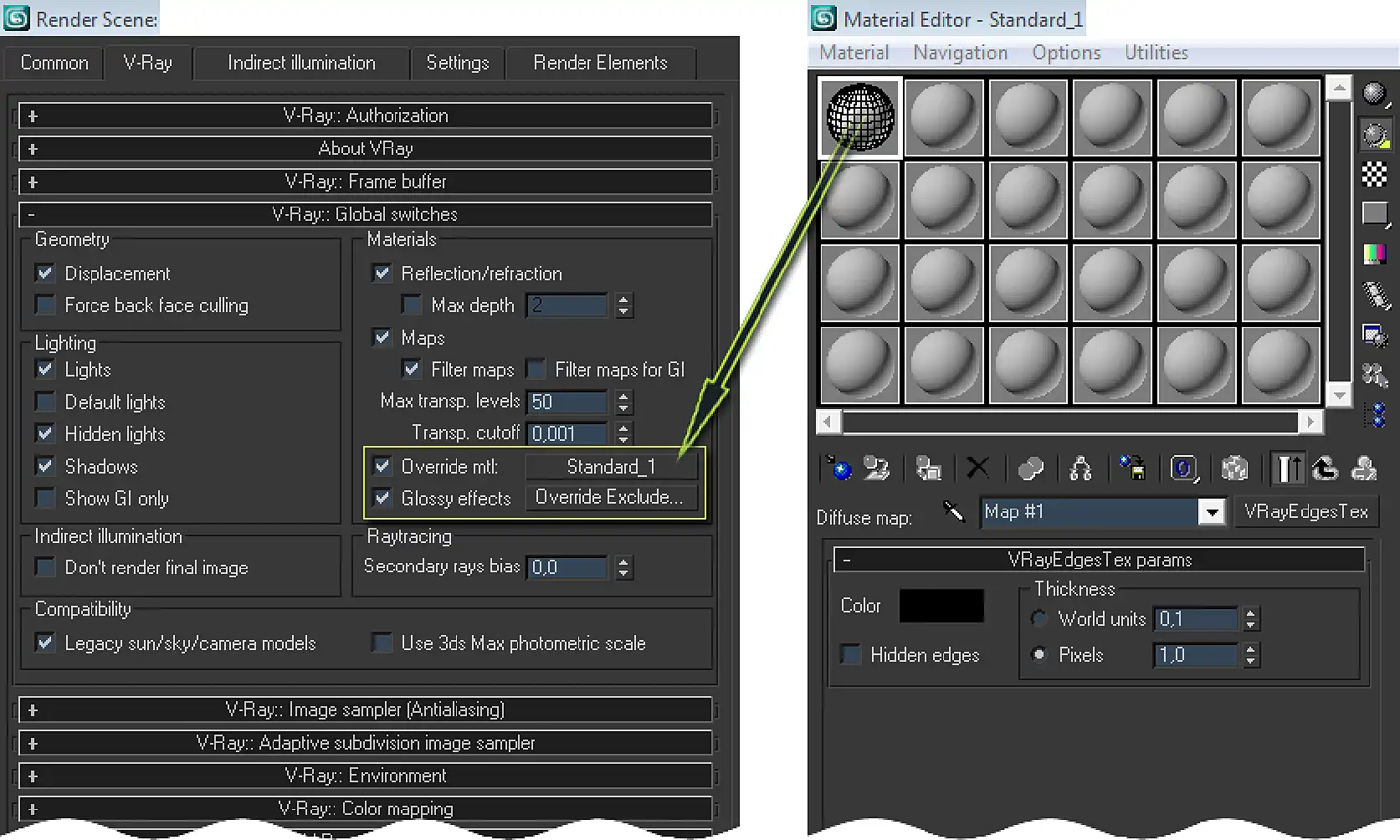
The Override Exclude... option allows you to specify which objects materials you do not want to replace with Override mtl material during rendering, if you need to.
Wireframe of Transparent Materials
When the scene contains only opaque objects, everything is quite simple. But in the case when the scene contains objects with transparent materials, simply overlapping it with opaque wireframe material will not look as we expected.
In our "fishy" example, we definitely want to see the topology of a 3D model of smoked mackerel itself through the transparent plastic of the packaging film. If we replace it with the opaque wireframe material, we will not see the topology of the fish under it, but only the topology of the package itself.
In our "fishy" example, we definitely want to see the topology of smoked mackerel 3D model through the transparent plastic of the packaging film. If we replace it (packaging film) with an opaque wireframe material, we will not see the topology of the fish beneath it, but only the topology of the packaging. In most cases, this is not our main goal, because what we should see under the transparent parts is mostly more important than the transparent object itself.
There may be many other examples, such as the crystal vase through which we expect to see the topology of the flower stalks, but they will not be visible only the vase itself; or car glass, through which the interior 3d model becomes invisible, etc.
The best and easiest way out of this situation is to leave such transparent objects with their native transparent materials. In most cases, this is the most rational approach. Transparent material does not violate the overall picture and, conversely, the combination of transparent and wireframe materials makes the final rendering more interesting.
Wireframe of Objects with Displacement
The case with 3d models with displacement, also should be noted separately.
The displacement is a technique of modifying geometry based on texture; that is, it shifts (displace) the vertices of the geometry by a distance (offset) according to the color of the displacement texture supplied to the displacement modifier, where white means maximum displacement, black - no displacement at all.
If it is a direct geometry offset modifier, such as the 3ds Max Displace modifier, it displaces the model geometry as it is, without additional geometry subdivision. In order to see small details displacement on a mesh, you must apply a mesh smooth modifiers by yourself.
On the other hand, some displacement modifiers, such as the material built-in modifiers based on Displace (VRayMtl) or Displacement (3ds Max Standard) channels, or the VRayDisplacementMod modifier tessellates the mesh of the 3D model with additional triangles. In this case, VRayEdgesTex is rendered before the displacement is happened. Therefore, it does not take into account the displaced (subdivided) version of the model. Even if you select Hidden edges option, only the base mesh (before displacement) edges will be visible on a render.
Adjusting Renderer and Lighting Settings for Wireframe Rendering
It may sound unexpected, but in most cases you do not need any additional settings for either renderer or lighting. You can use exactly the same scene where you render the colorful realistic image of this model. The same scene, the same camera, the same lighting and renderer settings. You only need to create the wireframe material as described earlier, utilize global material override option, and render an wireframe image. The only thing, it is better to do this in a copy of the original scene. Just copy the scene file, give it a meaningful name, such as "original scene name..._wireframe.max", and work there.
There are a few exceptions when you need to adjust something further, for example, when the lighting should be less bright due to white filling color of the wireframe material, and when the shadows should be denser. Or when the environment is bleeding too much or the background color is not suitable. But you can easily find a solution according to the situation. It is certainly not worth to describing all the possible cases and solutions here.
Isoline Wireframe Rendering
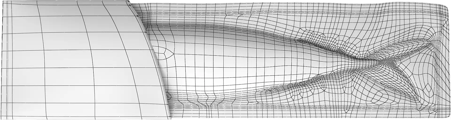
Another very important aspect of wireframe rendering is the density of the mesh at different levels of smoothing. If you created a 3D model with a subdivision-ready topology, you probably want to show not only the basic mesh wireframe with visible faceting, but the topology shown on the smooth model.
If you apply several smooth iterations to the model, its mesh quickly becomes too dense, and on the wireframe rendering can look like very dirty or even as completely black model.
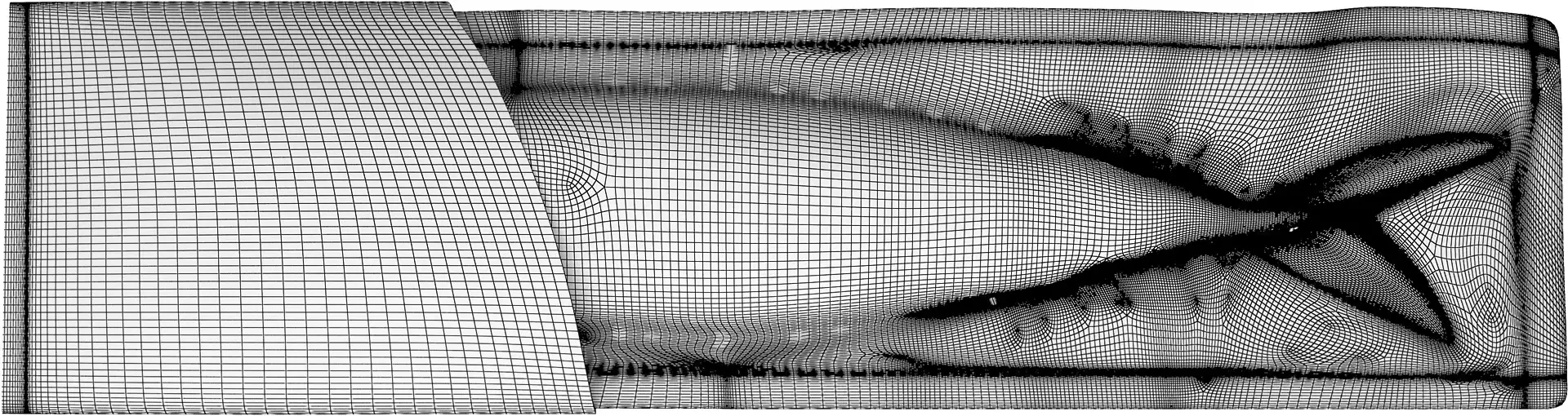
To solve the problem, there is a way to display the baselines of the topology, but on a highly subdivided mesh. This technique is called isoline rendering or rendering of isolines, where the edges of the base-mesh look like smooth isolines, and at the same time the edges of the dense smoothed geometry version are hidden.
The 3ds Max TurboSmooth modifier will help us with this. It has a special mode called Isoline Display.
All you need to do is apply the TurboSmooth modifier to the base mesh of the model, then set Iterations to required number and apply smoothing to the model by checking the Use NURMS Subdivision checkbox.
Finally find the Isolated Display option and check it too.
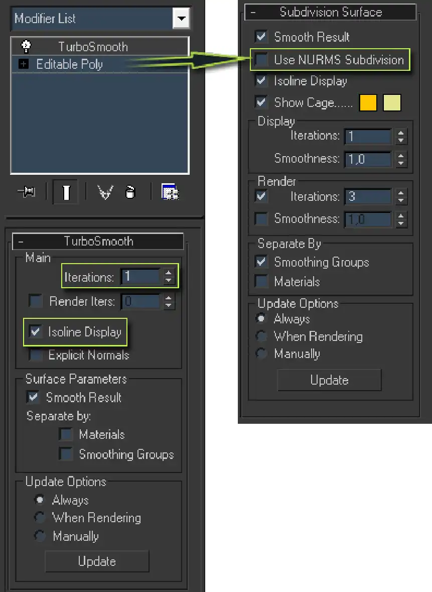
By the way, TurboSmooth is also built into the Editable Poly object. In case if you don't want to use separate modifier, you can go to its Subdivision Surface rollout and Use NURMS Subdivision from there it instead.
Interestingly, despite the fact that the isolines looks perfectly continuous in the viewport, the VRayEdgesTex map will render them more literally as a set of straight edges of smaller size. This is because it does not render an imaginary isoline, but simply traces that edges on a dense smoothed model divided by several iterations of smoothing. So it will looks on a render slightly dashed. Anyway, it's barely noticeable and the isoline wireframe renders still looks great even so.
Wireframe Rendering in Mental Ray
Other renders also support wireframe rendering. If you use 3ds Max, but do not use V-Ray, you can also make a wireframe visualization using its built-in visualizer - Mental Ray. In the Mental Ray renderer this can be done with a Composite shader and the Wire parameter from the Standard material.
To make a wireframe shader, first create a Composite material. Put white Standard material in the Base Material slot of Composite. This will be the polygons filling color. In the next available slot, also place the Standard material, but black. This will be the color of the topology edges. While you in this black Standard material, also check Wire property.
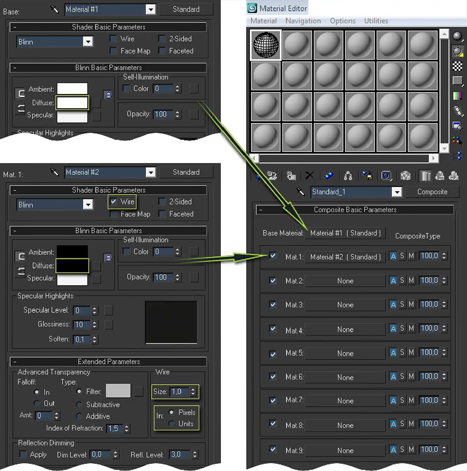
And here, the wireframe material for Mental Ray is ready!
In order to control the thickness of the Wire, you should go to the Extended Parameters rollout of Standard material and use there Size and In options in the section also called Wire.
The Composite material is supported only by Mental Ray. In 3ds Max Scanline, for example, you can use standard material with Wire parameter selected, but in this case only the skeletal wire frame (with no polygons visible) of the model will be rendered.
Mixing Realistic & Wireframe Renderings
You've probably seen a lot of portfolios where professional 3D artists first showcase their original artwork and then, to prove it's 3D, combine them with a mesh rendering where a realistic image seamlessly transitions into a wireframe. As a result, we see a realistic visualization with wireframe smoothly reveals underneath.
Compositing in Photoshop
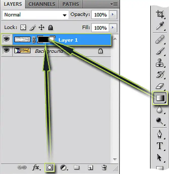
If you are familiar with Photoshop, this will be easy to do. You need both realistic and wireframe images. Add them both on separate layers of one file, realistic visualization from below, a wireframe from above. Then apply the mask on the top wireframe layer. Then, use black & white linear gradient tool on a mask. Under the black part of the mask you will see a realistic visualization, where the mask is white - wireframe.
When you are satisfied with the results, save the newly created mix of two renders and that's it!
Compositing in 3ds Max Only
If you are unfamiliar with Photoshop or do not use it, you can achieve the same results using only 3ds Max.
Such a simple compositing can be easily done with a standard 3ds Max map called Mix and a hidden but useful Material Editor's option called Render Map ... .
So, open Material Editor, select any unused material sample. Then place the Mix map in any map slot, for example, into the Diffuse map slot of the Standard material. Next, drag newly created Mix map from current material to any other unused material sample (drop the map onto material sphere in Material Editor). This way you get a map installed as a sample instead of a sphere in Material Editor. This is necessary step to get access to the Render Map ... option later.
Now go to that Mix map and place the image with realistic render into the Color#1 slot, wireframe image into the Color#2 slot, and the Gradient Ramp map into the Mix Amount slot.
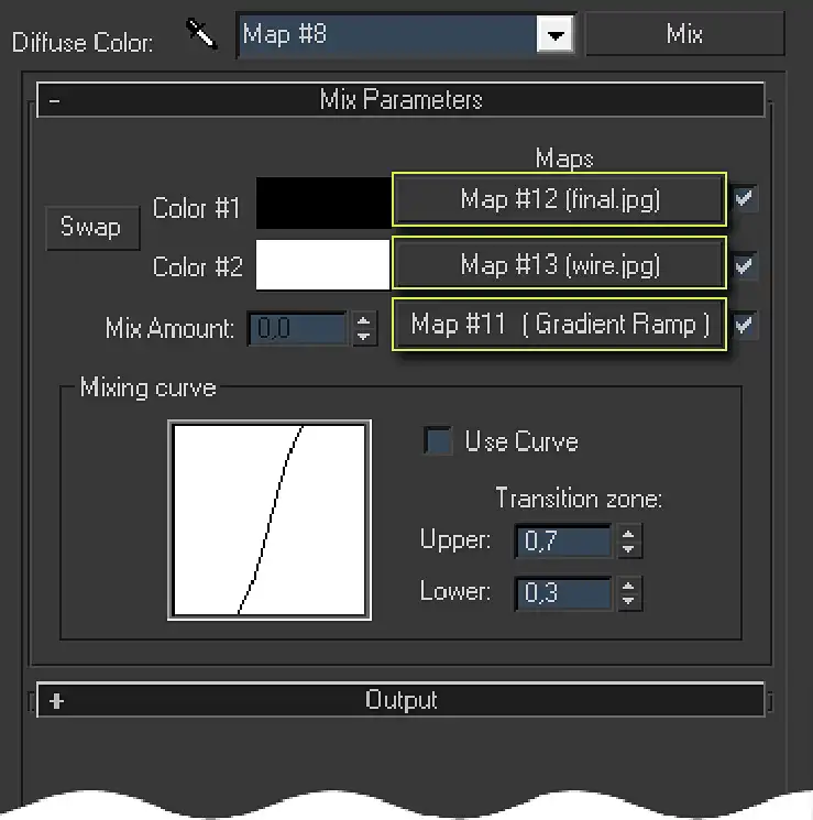
The Gradient Ramp mat is a standard parametric map of 3ds Max designed to generate gradients. It has a very simple controls, you will quickly understand what to do if you are not yet familiar with this map.
After adjusting the gradient, you can proceed to the rendering of the map.
Right-click on the Mix map in Material Editor. A context menu will appear. Select the Render Map ... option. You will see the Render Map dialog. In that dialog, set the width and height to the same values as the width and height of the realistic rendering you are using. Click Render. The Frame Buffer will appear with the result of Mix map rendering. Now you have a mix of realistic and wireframe renders.
As you can see, no additional software is required for such a simple compositing.
Conclusion
Show your skills in the best way, freely demonstrate wireframes of a complex models you created to the public, be proud of your work, and it will undoubtedly be appreciated by your colleagues and potential customers.
Have a nice wireframes renderings and presentable portfolios!
And as always, leave your suggestions and questions about this tutorial in the comments below.
There is really no difference. The so-called "clay rendering" is only a special case of shaded rendering. This is when a material is not just perfectly white with no shadows, but gray, which shows shadows. This type of gray shader simply visually resembles a "clay", it got this name only because it looks like a mineral.
Share
Please share if you like it!