Irradiance Map in V-Ray 1.5
An detailed explanation of how adaptive (biased) Irradiance map GI engine works and its advantage over unbiased Brute force. Here you will see exactly how IM samples cloud look like in three-dimensional space and it view-dependant nature. How it is built using different resolution pre-passes and how to control their resolution with Min rate: and Max rate: parameters. What should be the optimal values for fast, clear and detailed renderings.
This series of tutorials was originally written in 2010. Then the working version of V-Ray was 1.5. The idea of this series is, firstly, to explain all the important concepts of visualization in simple language on illustrated examples, and secondly, to provide a package of initial values or so-called "universal" settings for the renderer which are tested in practice, suitable for most scenes and allow you to achieve best balance between quality and speed (rendering time).
Since then, in the latest versions of V-Ray (currently V-Ray 5), some settings have been renamed, moved to other sections, hidden or completely removed from the user interface.
To learn more, read the Main 2020 Update.
This is a tutorial series intended to guide you through all the basic V-Ray rendering settings. It successively describes all the V-Ray-related tabs located in Render Setup: ... (F10 key) dialog.
You can use the navigation menu below to learn more about other tabs settings from other chapters.
V-Raytab: Antialiasing & Color mapping in V-Ray 1.5Indirect illuminationtab: Indirect illumination in V-Ray 1.5Indirect illuminationtab: Irradiance Map in V-Ray 1.5Indirect illuminationtab: Light Cache in V-Ray 1.5Indirect illuminationtab: Rationale for the Choice of GI Engines in V-Ray 1.5Settingstab: DMC Sampler or Speed vs Quality in V-Ray 1.5Settingstab: Ray Casting & Memory Allocation in V-Ray 1.5
Contents
Introduction
Hello everyone! We continue to setup a global illumination in V-Ray. In a previous tutorial on general GI settings and the principles of indirect Illumination, we learned what global Illumination is and why it is needed for photorealistic visualization. In this tutorial, we will consider the exact parameters and arguments for and against an Brute force GI vs Irradiance Map as the Primary bounces GI engine.
Exact Brute force GI
Brute force GI is a basic algorithm that establishes a fixed number of rays reflected from a point in the scene after hitting it by original ray of light. If you remember, it was previously considered that the light ray from the light source falls on the surface of the scene object and is divided into a number of other rays, which in turn, bombard other objects of the scene (remember the example of the dandelion). Of course, the more diffusely reflected rays of the indirect light will the direct light ray be divided into, the more detail and less noise will be on the final image.
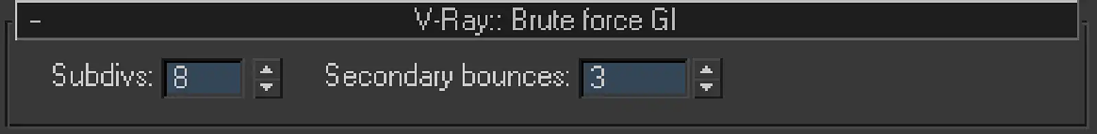
Screenshot of V-Ray:: Brute force GI rollout located in Indirect illumination tab of 3ds Max Renders scene dialog. Here present two parameters: Subdivs and Secondary bounces.
Subdivs is a parameter trivially influencing the number of reflected rays, to which every original light ray splits, when it reflects from the object of a scene. Numeric value Subdivs it is not the actual number of such secondary rays. The actual number of rays will be equal to the square of that number. That is, if Subdivs is 2, then this means that the original light ray will be divided into four rays after reflection; if it is equal to 4, the original ray will be split into sixteen secondary and so on.
Secondary bounces is the value that specifies how many times will the secondary rays interreflect further. It is active only if the Brute force algorithm is set as an algorithm for rendering Secondary bounces in the corresponding dropdown list, because in this case, it will calculate the right amount of interreflections. If the Brute force is set as a Primary bounces GI engine, the Secondary bounces parameter will be inactive.
Brute force algorithm is not adaptive, and simply calculates the GI for each pixel of the final image of the scene, not depending on its complexity, color and detail of objects. Thus, it spends the same amount of computing resources, both in clearly visible and in the unimportant parts of the scene. No wonder why it was named brute force :) We would also like to note that the Brute force GI is a direct calculation by the method of Quasi-Monte Carlo (QMC) and that is how it was called in earlier versions of V-Ray, which sometimes caused confusion when 3d artists have been long looking for a Quasi-Monte Carlo GI in the new interface.
The brute force of this algorithm is very irrational; its use leads to monstrous times for calculation, even on simple scenes at an adequate level of quality. Therefore, it is not worth to nominally use it in universal V-Ray settings as the render engine for primary or secondary bounces. Its use is justified only in special situations where other algorithms, because of their adaptability cannot cope with the calculation of small details in the scene, but more on that later.
Approximate Irradiance Map
Irradiance map is an adaptive algorithm of rendering global illumination bounces. The main feature of its work is to identify the most important areas of the rendered scene, calculate GI there and fill the GI information about the omitted areas by interpolating the information from the already computed ones.
In order to understand how it works and what the algorithm of Irradiance map is, let us look at map generated by it, which, by the way, called the same – irradiance map.
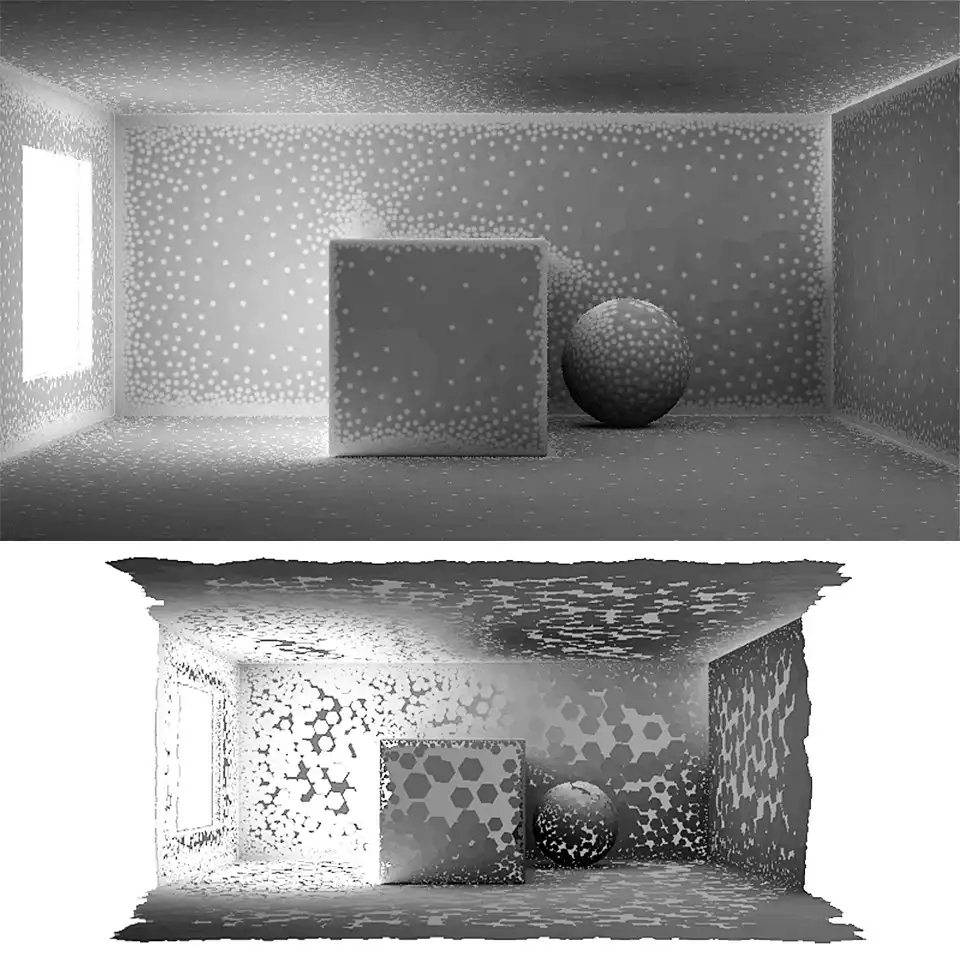
Test scene rendering with visible samples of Irradiance map. This image shows the number of the white dots, which represent the GI samples (samples cloud). The detailed areas have more of them, while the flat surfaces have only few on a great distance between each other.
In front of you is the test scene, which was used in the previous tutorial about the GI, with the same geometry and the same direct lighting as before. For clarity, were removed all textures from the scene materials, to not to obstruct the observation of the irradiance map. Look closely at the most crowded with white dots areas. This is the interior angles of the room, rounded ChamferBox angles, and places of close to each other parts of different objects, in particular on the side of the Sphere facing the cube, as well as the contact area of a cube with the front wall. These zones have the greatest importance in obtaining beautiful detailed global illumination.
It is set of these points is the irradiance map, which we see on the image. These points contain information about the color and brightness of GI in those exact areas. The rest of the image is filled with gray color. Gray areas on the irradiance map is part of the scene where irradiance map contains no information about GI. However, it is fully compensated by interpolation between the already computed points of irradiance map. In other words, Irradiance map calculates the most important areas only. After this, the missing information on areas, which were not computed, it simply compensated by interpolation, taking information about the color and brightness from the already existing ones.
It is quite obvious that the Irradiance map is an adaptive one. In contrast to the Brute force (BF), Irradiance map (IM) does not calculate samples for each pixel of a scene. It calculates samples for only important areas. Because of this, a very significant saving of computing resources is possible.
Irradiance map algorithm builds a three-dimensional map of points, containing information about the GI just on the surface of objects in the scene. In the volumetric view, the irradiance map of our example scene looks as follows:
The volumetric look of the Gi irradiance map produced by Irradiance map GI rendering algorithm. Here may be seen the actual 3d-ness of the GI map samples cloud and the disturbing of the samples in space. Here you can clearly see that in areas that are not directly visible from the camera view, there are no samples at all.
If we look at shown above second and third screenshots from special utility called Irradiance Map Viewer, we can clearly see not only the fact of three-dimensionality of irradiance map, but also its dependence on the view of camera, through which the rendering of the scene is performed. In particular, immediately striking eye the lack of points on the GI on not visible in the camera frame parts of the cube and on the other side of the room, which is located behind camera.
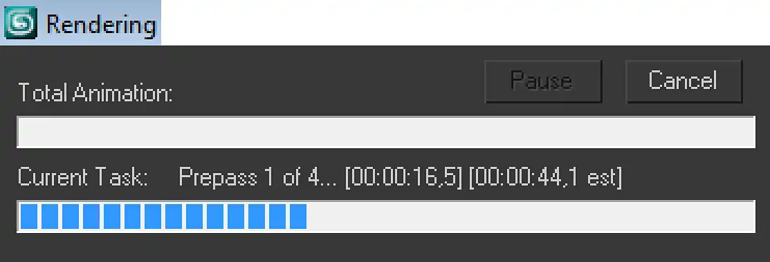
Screenshot of the Rendering window that pops up and stays along all rendering process. Here showed the Current Task of the IM calculation. Exactly is is a Prepass 1 of 4 means that the first of total four prepasses is performing at the moment.
In IM, the "probing" of important places in the scene in which the GI calculation is performed is implemented very elegantly. It uses the concept of undersampling, previously described in the first tutorial of this series. At first, GI samples cloud is calculated on lowest resolution for all scene details, which is usually less than the rendering resolution. This calculation is just not adaptive, as calculation with BF algorithm. After that, from the obtained data, the most important areas are determined, that is evaluating the very same areas where the more accurate rendering should be performed. Then the next higher resolution rendering takes place, but only in the required areas. This procedure is repeated several times step by step, each time increasing the resolution, and so, until it reaches the maximum specified resolution of the IM. The minimum and maximum resolution of IM rendering are set in its parameters. The step of calculations differs in twice more or twice less resolution, which is four times by area of the image in pixels. For example, when rendering resolution is 800 by 450 pixels, the next step of undersampling is 400 by 225, the next one is 200 by 113 and so on. It is worth noting that IM can use both the undersampling and supersampling. That is, IM can be calculated on less and on larger than the actual rendering resolution, in an even number of times, resolutions.
Each phase of the GI rendering called pass. The pass, which determines the important areas of the scene, called Prepass. The progress of passes calculation, their total number, and what prepass is calculated at the moment, can be observed in the Rendering window, which pops up after starting the rendering.
Let us see, how IM calculation looks like on the example of four prepasses.
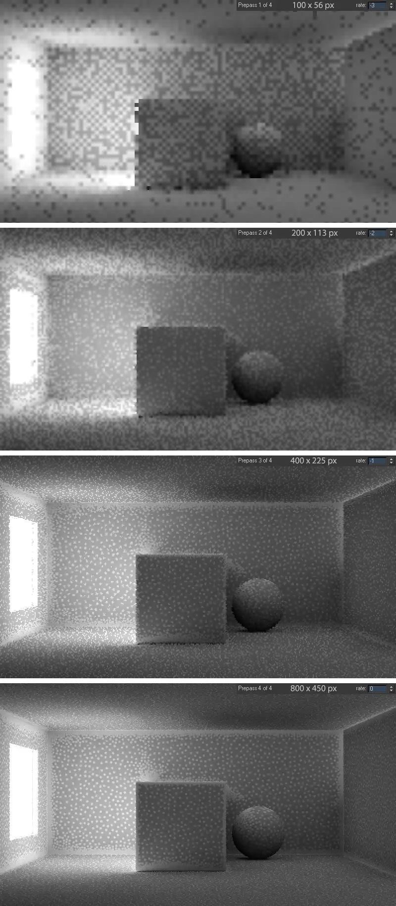
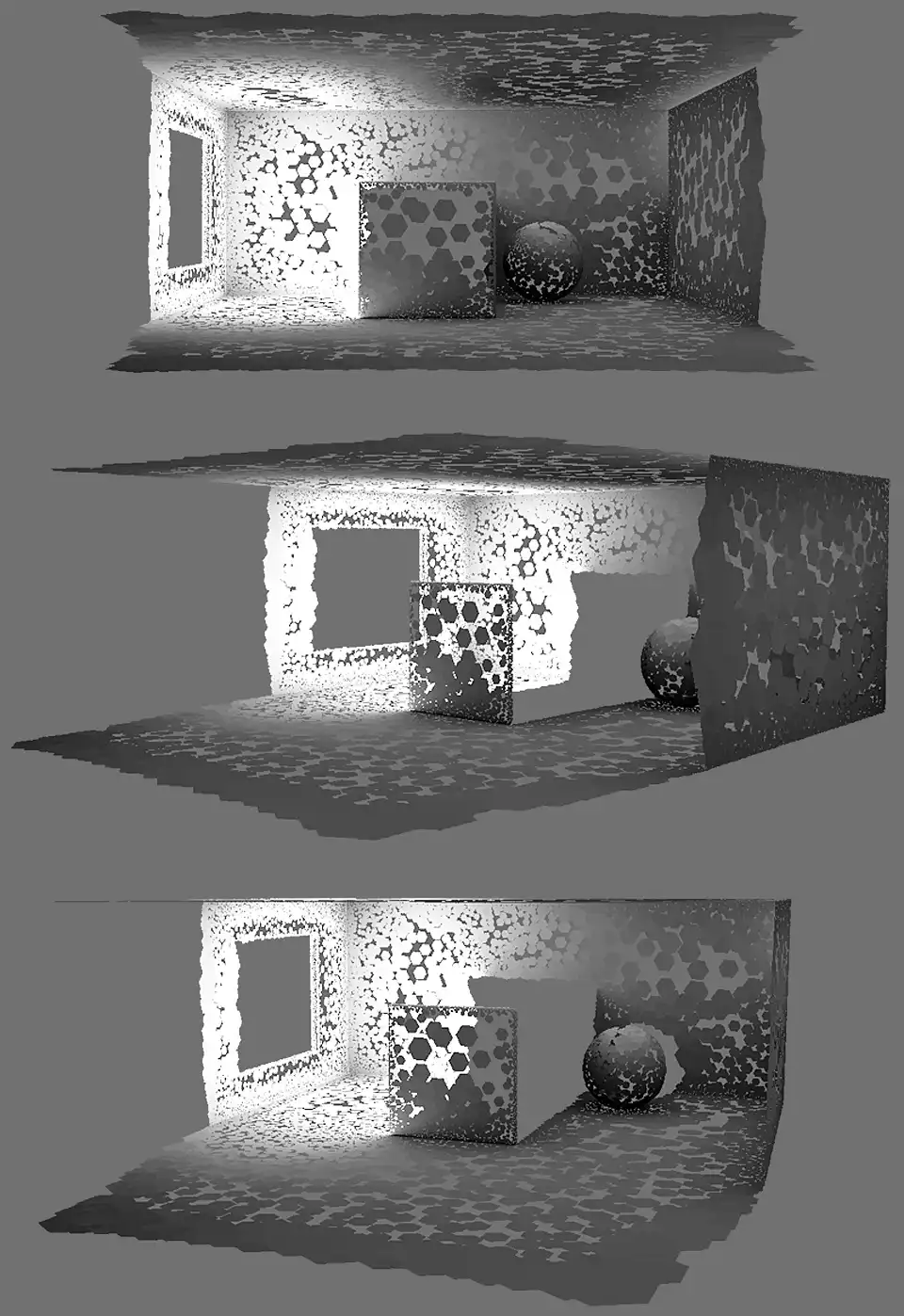
Four test scene renderings with visible samples. There are four step by step prepasses of Irradiance map. The first one has no higher density of samples in detailed parts of the scene, while others have them. The last fourth prepass shows the final samples distribution on the Irradiance map. All renderings have showed IM resolution.
In this example, the maximum resolution of IM rendering is a resolution of 800 by 450, equal to the resolution of the rendering of the final image. To fully identify important areas, first used three undersampled prepasses at lower resolutions: 100 by 56 in the first prepass, 200 by 113 in the second prepass, and 400 by 225 in the third. Together with the final prepass, there are total four IM prepasses.
Look at the first prepass. You may notice that it had not allocated any areas, the entire image calculated equally with the same accuracy as the BF algorithm does. But completely different picture can be seen already at the third and especially the last fourth prepass. It is clearly apparent how the IM algorithm highlighted the important details of the scene, strewed them with GI samples, and significantly thinned out flat not detailed surfaces. They are unimportant the parts, such as walls planes, the flat face of the cube, etc. They have only a few points that will later be simply interpolated between them by IM algorithm, filling the empty zones. Also, we can immediately see that the size of samples with respect to the entire image at different prepasses is different, because the higher the IM rendering resolution, the lower the value of a single sample, and so more detail and more accurate irradiance map is.
It is not hard to guess that GI map, calculated with IM even on the full final resolution without advance prepasses, so without calculating the important areas will be just as tough and not adaptable, as in the case of GI rendering using the BF algorithm. The time to calculate it will certainly be nearly as long, as in the case of BF.
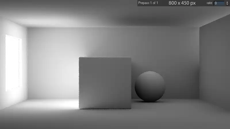
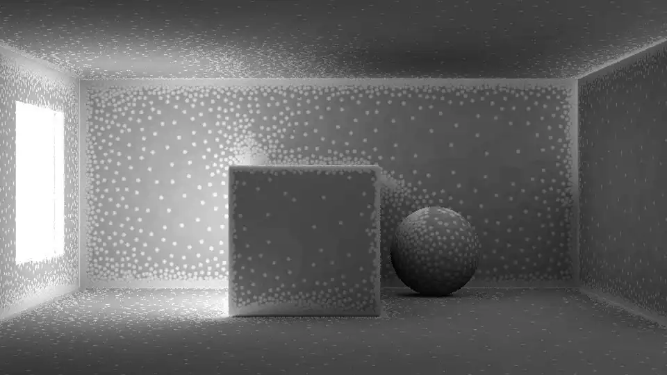
Rendering of the test scene with the visible IM samples. It may seem that here no samples at all. But in fact the whole image is filled with small and very densely placed samples. They are equally placed on the detailed parts as well as on the not important flat homogenous surfaces.
This image shows the Irradiance map, calculated by one prepass right at the final resolution. When looking at it, it seems that there are no samples at all. However, it is just the opposite. All that is seen in this picture, these are all samples, very tight-studded the each pixel on final resolution. Thus, the irradiance map is not concentrated in some important areas; it completely covers all scene objects visible from the camera. Obtaining such a dense map entails such as many calculations. In particular, all four prepasses in the first case were calculated in 5 minutes, while calculation of only one pass in the second case took 50 minutes of computing time. The difference is more than obvious. Make no mistake that in the second case, the quality of the final image will be substantially better than in the first, because of richer map. The fact is that the unimportant areas of the scene represent mostly flat surface of one color; the color of GI there, is homogeneous and without details in both cases. However, important areas of the scene, in fact, that were calculated with and without adaptation, are equally detailed. That is why there is no point in spending ten times more computing resources on rendering homogeneous flat surfaces to get essentially the same result. We believe that the scale of time saving, when calculating the with IM, comparing to the time of calculation with BF, is quite obvious.
When the map of important points that contain the GI color information, has been calculated, the interpolation of missing GI points is starting. Then on rendering, in each point, as in the case of BF, performed calculation of a fixed number of secondary light rays over the hemisphere, as described in the previous tutorial.
Irradiance Map Basic Parameters
The parameters located at the V-Ray:: Irradiance map rollout are responsible for the areas that the IM algorithm will consider important, the number of secondary rays that IM will generates for calculation of each IM cloud point, and the resolution at which the scene details need to be probed.
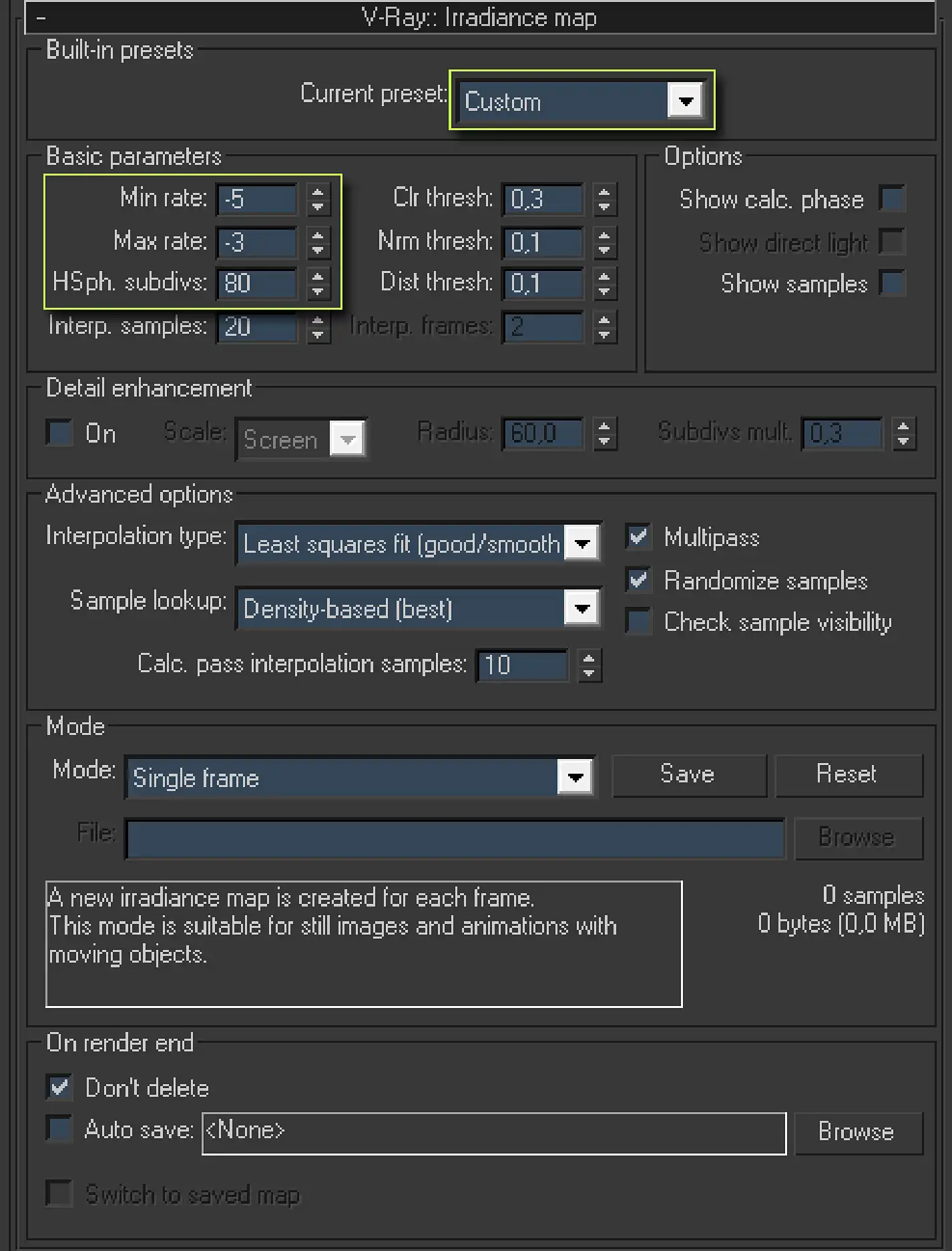
Screenshot of the V-Ray:: Irradiance map rollout from Indirect illumination tab of the Render scene 3ds max dialog. There are a lot of parameters. The first, is a Built-in presets area that has only one drop-down list called Current preset. The Basic parameters zone contains: Min rate:, Max rate:, HSph. subdivs:, Interp. samples:, Clr thresh:, Nrm thresh:, Dist. thresh:, Interp. frames:. The Options zone contains: Show calc. phase, Show direct light, and Show samples checkboxes. There are also Detail enhancement, Advanced options, Mode, and On render end zones.
Current preset is just a quick set of preset values for the main parameters of IM. Dropdown list with these sets is in the Built-in presets zone. The purpose of each of them can be easily understood by their names, they speak for themselves: Very low, Low, Medium, Medium animation, High, High animation, Very high. However, the greatest interest to us is the Custom option. As its name implies, this value allows us to manually configure IM. Feature of Current preset option is that if you select one of the presets, and then select Custom, then numeric fields of IM parameters will keep the values of the last preset. By default settings, IM is preset to 8High, it is this preset we should choose for the start and then change the basic parameters of the IM, selecting the Custom.
Next, the Basic parameters zone options come. These are obviously the basic IM parameters.
Min rate is a value that determines the resolution of the first prepass of GI.
Max rate is a value that determines the final resolution of rendering GI or simply the resolution of the last prepass.
As we already know, the IM algorithm with a few GI calculation steps selects the most important and detailed areas. If you look at the examples above, in the upper right corner you will find the value of rate, which determines the resolution of current prepass in rendering IM. Rate value 0 (zero) means that the calculation of GI will be in a resolution equal to the resolution of the final rendering. Rate value equal to -1 means that the calculation of GI will be in a twice lower resolution than the resolution of the final image. Rate value equal to -2 means that the calculation of GI will be in a twice lower resolution than the resolution of -1 rate, which means four times less than the final image resolution. By analogy, the rate value equal to 1 would mean that the calculation of GI will be doubled comparing to resolution than the resolution of the final image, etc.
The Adaptive subdivision, anti-aliasing algorithm, uses a similar concept of undersampling and supersampling, this was discussed in detail in the first tutorial of this series.
Algorithm of Irradiance Map is a very flexible and high-tech tool. Although it seems logical to render a final prepass for the GI at the final resolution of the render, i.e., with Max rate: equal to 0, in practice it is absolutely excessive to do this because of the small difference in quality, and the huge difference in computational cost.
The following examples illustrate this:
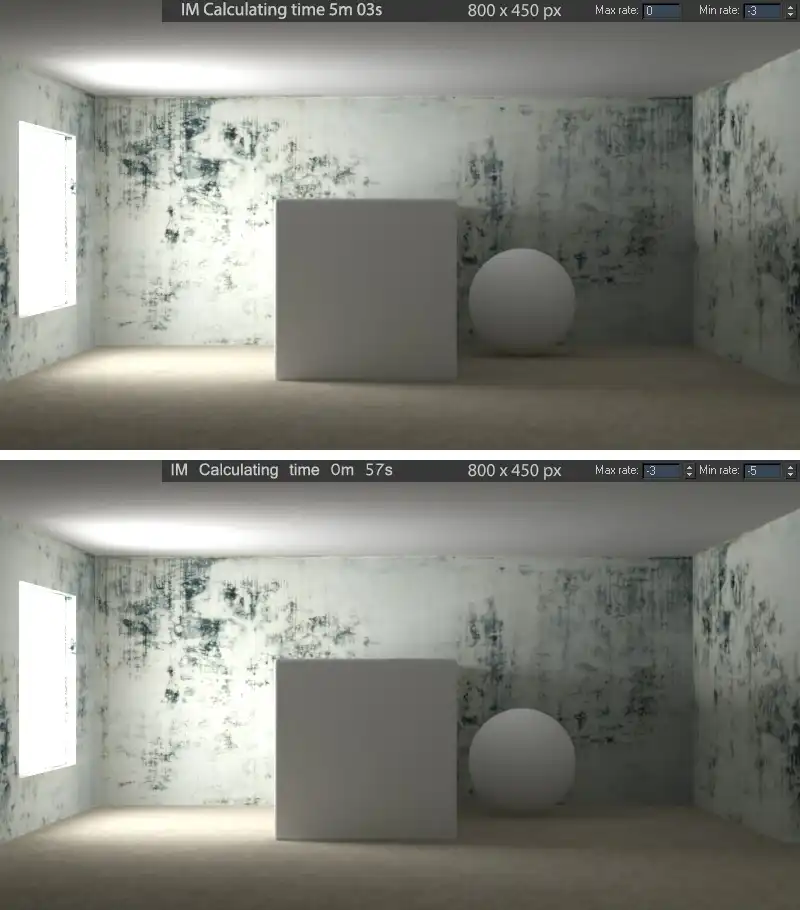
Test scene rendering with different Min and Max rates. The first rendering shows beautiful image with the long rendering time. While the second rendering shows the quite acceptable image quality with the 5 times less rendering time.
On the first image, where the IM has been calculated on the final resolution of the rendering there is a little more clear and dense shade under the sphere than on the second image, as well as more precise and sharp shadow at the bottom of the cube, especially seen in its left corner. This is because in the first case, IM has a lot of small details, while the latter are interpolated from a smaller IM resolution. However, the render time of IM in the first case (Max rate: 0) by more than 5 times greater than when the last prepass was calculated at 8 times lower resolution (Max rate: -3). Five minutes and three seconds against fifty-seven seconds. At higher resolution and more complex scene, the time difference calculation IM will be even greater. At the same time, at high resolutions such as 2500 – 3500 pixels by a side, which is by the way should be used in the final rendering, this difference will be less noticeable due to the overall resolution increase. In addition, this slight and pale blur of details in a few minutes elementary eliminated in 2d graphics editor. In practice, the values of the Min rate: -5 and Max rate: -3 is sufficient for the good photo-realistic rendering, and these values should be set in start V-Ray configuration.
Parameter HSph. subdivs: (in a more expanded form HemiSphere Subdivisions) is the number of rays of GI, reflected from a point on the surface of the object. This parameter determines the amount of diffuse light rays taken of each secondary point IM, as mentioned earlier, in the form of a hemisphere. That is a complete analog parameter to a Subdivs in BF algorithm. In most cases, the HSph. subdivs: value, equal to 80 is enough and that it should be set for universal V-Ray configuration.
Interp. Samples: is the parameter that determines the quality of interpolation of the IM. Remember the examples with IM samples, where the samples were marked with light dots, and missing areas with gray color. Interp. Samples: determines the quality of interpolation of not important gray areas with missing information, from the white-dotted important areas. The higher the value of Interp. Samples:, the higher the interpolation, resulting more blurred GI, while at low values of Interp. Samples: GI map is less "soapy", but more noisy with lots of artifacts. Default value of 20 samples is enough, and this value should not be changed.
As we already know, IM with help of prepasses feels for to the scene to identify its most detailed parts. IM does so, based on previous prepasses information, and it is guided by three main critical in terms of details properties. This is color, difference between the normals, and the relative position of objects. In the IM, these properties are presented with Clr thresh:, Nrm thresh and Dist thresh parameters respectively.
Clr thresh: determines the sensitivity threshold of the algorithm IM to the colors of the scene. The higher the threshold, the less color changes on the objects of the scene will be considered as important areas and the easier will be the calculation of IM. Lowering the sensitivity threshold of the algorithm will make IM more sensitive to color changes in the scene and would create more detailed IM, and so the better pictures. Clr thresh: parameter value equal to 0.3 is quite acceptable to create an acceptable IM and in universal V-Ray settings we should use it.
Nrm thresh: defines the sensitivity threshold of IM algorithm to the scene geometry, in particular to the intensity of change of the object’s normals in it. The lower the threshold, the more geometric details on the objects of the scene will be considered as an important area, respectively, higher quality will be the final image. The parameter Nrm thresh: equal to 0.1 is enough for a well-detailed IM and it should be used in universal V-Ray settings.
Dist thresh: defines the sensitivity threshold of the IM algorithm to neighboring geometric surfaces in the scene. The higher the threshold, the farther each to other surfaces will be considered as an important area and better will be the final image. Looking at the showed above example, you can easily understand the difference between parameter Dist thresh: and parameter Nrm thresh:. If from Nrm thresh: in this scene will depend the density of the IM in the corners of the room, thenDist thresh: will determine the detail of IM in the zone of the close location of the sphere and cube to each other. It should be noted that, when the thresholdDist thresh: is lowered, it will take into account only the smaller distance between the surfaces of objects, thereby reducing the density of the samples of IM, and hence the quality of the final image. Pay attention that it is in contrast to the Clr thresh: and Nrm thresh:, where the decrease of threshold improves image quality. The parameterDist thresh: of 0.1 is enough to create a good IM and we should use it in universal V-ray settings.
The last parameter, located in the zone of Basic parameters, it is inactive Interp. frames:. It is responsible for a number of irradiance maps, calculated for different frames of animation in the mode of Animation (prepass), which V-Ray will use to render the current frame in Animation (rendering) mode. It is in the last case, this option will be active and available for change. However, these are very specific modes of IM, which will be described in the tutorial on rendering various types of animation in the V-Ray. By default, in the universal V-Ray settings this option may be left unchanged.
In Options zone of the V-Ray:: Irradiance map rollout can be enabled options, which are responsible for IM rendering in the frame buffer. These options enabling let us to observe clearly the IM prepasses calculation, to show direct light with the GI on the prepasses rendering and to watch the location of samples on the IM. For these functions response parameters Show calc phase, Show direct light and the Show samples, respectively. These are all test functions that do not affect the IM rendering, and in the universal starting V-Ray settings they should not be activated.
Irradiance map Detail Enhancement
The next area of IM parameters is the Detail enhancement.
As we know, the main highlight of IM is the calculation of important details of scenes with prepasses at lower resolutions. Option Detail enhancement allows us to create a hybrid between an adaptive, but making a little fuzzy samples map IM algorithm and a rough, but precise in details, Brute Force.
When the function Detail enhancement is activated, IM, as well as before, uses prepasses to calculate the details of the scene. However, at the last calculation pass, when the final information on the detail in the scene is obtained, the algorithm Detail enhancement comes into play. The principle of Detail enhancement work is that GI samples of the most important areas are calculated by the algorithm Brute Force at full resolution of the final rendering, without undersampling. All other areas, as in the normal mode of IM, are calculated by interpolation.
The algorithm of Detail enhancement for the determining of what samples in important areas should be calculated, based on the principle of the algorithm similar to the Ambient occlusion (AO), but, in contrast to AO, Detail enhancement algorithm takes into account the direction of light.
It is worth to note that when Detail enhancement is activated, IM algorithm is used only to determine the detail of the scene, and direct rendering of important details lies on the BF component of Detail enhancement. Knowing this, if the option *Detail enhancement *is active, we can lower all the parameters of the IM, except Interp. samples. Parameter Interp. samples can even be set to larger values.
Algorithm is activated by setting the tick in the checkbox On. Then become active settings such as Scale, Radius and Subdivs mult..
Scale defines the units of measurement of the following Radius parameter.
Radius is the value of the hemisphere radius, which defines the area in which the BF will calculate the GI samples from the reference point. Location of reference points of BF, as mentioned above, is determined at the stage of calculations of detail of the scene with prepasses.
Subdivs mult. is in fact a complete analog of Subdivs parameter of the BF algorithm, which determines the number of diffuse rays. It is set as a percentage of the current HSph. subdivs: value.
To better understand what is the radius of the hemisphere, and what hemisphere point we are talking about, we should be closer acquainted with the concept of AO. Explanation of this concept is beyond the subject of this tutorial, but it will be discussed in detail in separate article on AO and, in particular, areas of application of the parametric VRayDirt map. In any case, Detail enhancement is a specific option, which greatly reduces the adaptability of IM and significantly increases the time of GI rendering. That is why it should not be activated unnecessarily and, of course, in the universal V-Ray renderer settings also.
Irradiance Map Advanced Options
Next in the IM settings is a zone of Advanced Options.
Interpolation type is drop down list that allows us to choose the method of interpolation if IM samples, i.e., the algorithm that fills the missing areas in the IM, getting the absent sample data from already computed ones. This list contains four methods, they are Weighted average (good / robust), Least squares fit (good / smooth), Delone triangulation (good / exact), and Least squares with Voronoi weights. Technically, they have different mathematical principles to calculate the result. It is absolutely no need to delve into how they work. End user need only to look at the clues given in parenthesis at the end of each of them, and immediately become clear about their features. Optimal interpolation method is the default Least squares fit (good / smooth). That is it worth using in the starting V-Ray configuration.
Sample lookup is a drop-down list, allowing us to select a method that determines which of the calculated IM samples will take part in the interpolation of missing samples in the surrounding areas. There are four sample selection methods, they are Quad-balanced (good), Nearest (draft), Overlapping (very good / fast) and Density-based (best). These also are algorithms, each with its own mathematical peculiarities in the methods of selecting the desired samples, in which it is not necessary to delve without special need. Similarly to the Interpolation type methods, the tips in parenthesis next to their name perfectly explain their features. By default, the best method of Density-based (best) is set and exactly it we may use in universal V-Ray settings.
Calc. pass interpolation samples - a value that specifies the number of computed samples that will guide the IM interpolation algorithm during the last calculation pass. Nominally assigned value of 10 samples is enough to get good results. It should be used in universal settings of V-Ray.
Multipass is a feature that allows the current IM prepass to be able to use absolutely all available samples, calculated for the current particular moment. That is to say, the samples from previous lower resolution prepass, and samples that are already computed in the current own prepass.
Irradiance map is computed as the final render, in many threads to fully utilize the potential of modern computing systems, which are often multi-threaded through multiprocessing and multi-core. Initially, when calculating IM by multithreaded system, every piece of IM is calculated by a separate thread, independently each from other. The data for this calculation is taken only from the previous prepasses. Because of this, it turns out that each piece of calculation of IM, without information about the surrounding portions gives inconsistent with them results. On the calculated in this manner IM become evident the boundaries of those portions in the form of lattice.
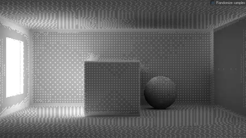
Rendering with Multipass turned off. It demonstrates that the obtained this way IM has evident lattice formed by rendering portions, that were not matched.
Look closely at the picture. There are clearly visible linear boundaries of IM calculation per-thread portions. For example, this effect is very noticeable on the sphere and on the wall to the right, on the ceiling above the cube.
Enabling of Multipass function allows the IM algorithm to use information about the current prepass samples. That is, when rendering each portion, it allows the IM algorithm to use information about the adjacent calculated portions, giving a consistent smooth result. Thus, in practice, Multipass function allows to smooth the boundary between the IM calculation portions, giving homogeneous IM, without any visible artifacts in the form of a lattice. In the universal starting V-Ray configuration, this function should always be kept active.
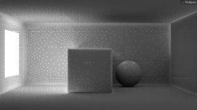
Randomize samples is a feature that allows to generate samples of IM in a random order, making IM more realistic. Nominally, the IM algorithm selects the samples on scene objects with regular intervals, resembling a grid, even if the considered above option Multipass is enabled. This effect clearly can be seen in the image below.
Test scene rendering with Randomize samples turned off. It shows that by default, IM samples are placed with the predictable order, which can lower the photo-realism of the obtained image.
To resolve this regularity, which betrays the computer origin of the image, and prejudices photorealistic renderings, function Randomize samples in universal V-Ray settings we surely must keep activated.
Check sample visibility is a feature that allows us to interpolate the samples of IM, only being in sight of each other. Very often, due to the low density of IM, in the process of interpolation of missing samples, the IM algorithm takes the neighboring samples that fall within the zone of sampling for a given point, even though they may be located outside the visible area relatively to each other in the scene. For example, we have a bookcase with a thin wooden shelf, lying close to the rear of this bookcase. On the top of the shelf is a light and it illuminates shelf’s upper part. Under the shelf, direct rays of light in no way can fall. Nevertheless, beneath a shelf at the rear can easily appear bright spots, despite the fact that they simply cannot be there. This happening because the IM algorithm to interpolate the missing samples in the area below the shelf, takes adjacent samples from the upper part of the shelf, without considering actual geometry. To avoid this, the IM interpolation algorithm is necessary to know that we want to check what samples are in the zone of direct mutual visibility, and what are not. Of course, such a check would require additional computational resources.
It is better to look at Check sample visibility example from V-Ray Help, it perfectly illustrates how this function works.
This is a very useful feature, however, in most scenes, the above-described artifacts are absent, and there is absolutely no need to always verify visibility of samples, needlessly wasting computing resources. In the universal starting configuration of V-Ray, feature Check sample visibility should be disabled.
In areas Mode and On render end we can set the IM working mode, needed for animation rendering. We can specify a folder and name on the hard drive, under which the computed IM can be saved. As mentioned earlier, to the animation in V-Ray a separate tutorial will be devoted, in which these options will be discussed. In starting universal V-Ray settings these options should be left untouched as they are by default.
The last thing you should pay attention to is that the Irradiance map algorithm designed to simulate a first diffuse bounce of light only! This means that it cannot be used as a Secondary bounces GI engine. In any case, you will not be mistaken, because in Secondary bounces drop down, the IM option is simply absent.
Conclusion
In this tutorial, we were introduced in detail to important aspects of two GI algorithms, they are straightforward and exact Brute Force GI and biased approximate Irradiance Map. And we chose to use adaptive Irradiance Map as Primary bounces GI engine, because it allows us to get acceptable results at lower computational costs, ie much faster. In particular, we carefully researched all the details, aspects and settings of IM and were able to clearly see the impact of each important settings on numerous examples.
See you in the next chapters of this tutorials series!
You're kind of right, but let's just look at what the official manual says:
The number of GI samples that is used to interpolate the indirect illumination at a given point. Larger values tend to blur the detail in GI, although the result is smoother. Smaller values produce results with more detail, but may produce blotchiness if low Subdivs are used.Color interpolation is always about reduction of a certain amount of data to one value. In our case, this is the calculation of the color of one IM point, by reducing a certain number of adjacent points colors. I say reducing because I have no information about what exactly is happening, but for simplicity let's assume that this is just a calculation of the average value, ie (sample1 + sample2 + ... + sampleN) / N = NewSample.If, for example, Interp. samples = 20, this probably means that to calculate one particular NewSample, 20 adjacent samples will be taken. Of course, when you mix other colors into one to get a new value, the new value will not be clear or detailed, it will be blurred, artificially reproduced. The more samples taken, the more blurred the result. For example, we have two cubes next to each other, one green, one red and gray gap between them. When the color of the gap is calculated, the green and red colors of the cubes will be mixed with the gray color of the gap. As a result, instead of a gray gap, it will be a dull yellowish color between the cubes. So, instead of sharp devision, we will get something average between.On the other hand, if you reduce the Interp. samples value, and if there are not enough samples on the gap, it may happen that the NewSample color will be zero or absent. And on the visualization it will look like a dark spot or blotch.And here we are at the point where it is more of a philosophy than a strict term. Which is better, a blurry but not blotchy render or a sharp and detailed render but with lots of blotches on most small details? We prefer to think that the first case is better, despite the blurriness, because blurriness is not so critical for GI. But muddy, blotchy artifacts are definitely not what you expect from a realistic visualization. That's why we wrote that Interp. samples it is about the quality of interpolation, because it so in a sense. However, if you continue to increase Interp. samples, you will get 'flying' objects because of blurry GI underneath. And that's why, we said that value of 20 is optimal. It is prevent lot of blotches but still not cause redundant blurriness. So I can't agree with you that you need to increase Interp. samples. more than 20, especially whan you have a good quality Irradiance Map. In this case, I even suggest doing the opposite, revealing more details without worrying about 'dirt' in the corners. It makes no sense to increase the blurring of the IM whan there are already enough samples in it.Max rate -3
I agree with you again that in some cases -3 is not enough and you can increase it up to, say, -1. But 0, to be honest, it contradicts the philosophy of adaptability or approximation. As far as I understand, the approach of the Irradiation map is based on two pillars. Probing, is when IM begins to determine where more samples are needed, starting with the lowest resolution (Min rate), to calculate as few samples as possible at the final IM resolution (Max rate). And, lets call it 'undersampling', when the maximum (final) resolution of the IM is lower than the actual resolution of the final render. Because IM is no better than Brute force, it is actually worse, less precise, because it is a shortcut technique, that reduces rendering time by sacrificing detail in less important areas, and renders GI map at a lower resolution. Max rate 0, means IM rendering at full resolution of a final render. In this case, you not exclude probing, but completely eliminate undersampling. Why use blurred approximate IM if you don't utilize its main advantage over precise exact BF? It doesn't make sense. The difference, in terms of rendering time, between IM on full resolution vs BF - will be insignificant, but the loss of details will be meaningful. I would say that if you have a situation where you need to to render IM at full res, there is definitely something wrong with the scene setup. But ok, let's assume it is just super complicated scene with a high density of small details, maybe you should consider to use BF instead? It may be a little noisy, but much more precise.In any case, it is very cool that you comment on the essence of the content and thoughtfully read what is written here. I am very grateful to you for the notes, they help a lot to improve the quality of the content and perhaps our discussion will help to somwane else to understand what's what.Of course, you are free to use your own approach, including Max rate 0, but, if you can afford (waiting time and computation power) rendering IM at full res, at least try to compare it to a much simpler BF. It has way less settings than IM, and it is more convenient and predictable in use.Cheers!
Share
Please share if you like it!