Light Cache in V-Ray 1.5
Photon map and Light cache GI Engine's review. It explains their limitations and advantages. Here you will learn what Light cache cells are and what they look like on clear examples. How Light cache stores direct light and calculates diffuse reflections. Why do Light cache need filters and what's the difference between pre-filtering and filtering? And of course, tutorial will explain an optimal settings for fast and realistic rendering with Light cache.
This series of tutorials was originally written in 2010. Then the working version of V-Ray was 1.5. The idea of this series is, firstly, to explain all the important concepts of visualization in simple language on illustrated examples, and secondly, to provide a package of initial values or so-called "universal" settings for the renderer which are tested in practice, suitable for most scenes and allow you to achieve best balance between quality and speed (rendering time).
Since then, in the latest versions of V-Ray (currently V-Ray 5), some settings have been renamed, moved to other sections, hidden or completely removed from the user interface.
To learn more, read the Main 2020 Update.
This is a tutorial series intended to guide you through all the basic V-Ray rendering settings. It successively describes all the V-Ray-related tabs located in Render Setup: ... (F10 key) dialog.
You can use the navigation menu below to learn more about other tabs settings from other chapters.
V-Raytab: Antialiasing & Color mapping in V-Ray 1.5Indirect illuminationtab: Indirect illumination in V-Ray 1.5Indirect illuminationtab: Irradiance Map in V-Ray 1.5Indirect illuminationtab: Light Cache in V-Ray 1.5Indirect illuminationtab: Rationale for the Choice of GI Engines in V-Ray 1.5Settingstab: DMC Sampler or Speed vs Quality in V-Ray 1.5Settingstab: Ray Casting & Memory Allocation in V-Ray 1.5
Contents
Introduction
In this tutorial, we continue or, better said, complete our familiarization with the various GI engine's of V-Ray renderer. Here we will look at a theoretically interesting but outdated and rough Photon map, as well as progressive and relevant today Light cache. Both solutions, of course, are designed to simulate diffuse reflection of light in 3D scenes. As you may have guessed, we will also take a detailed look at all the important Light cache settings in the illustrated examples and surely will learn about its optimal settings.
Conservative Photon map
It is an outdated rendering engine, the basic concept of which is that the light source bombards all scene objects by portions of energy called photons. After that, being formed a so-called photon map, that is three-dimensional map of photon’s contact points with surfaces. The each point stores information about the brightness and color of the indirect illumination. In general, such map is similar to a map, which obtained by Irradiance map algorithm.
The principle of photon mapping is relatively easier to understand compared to how the Irradiation map works.
In the Irradiance map, creation of global illumination begins with a vector from the camera, which is fly into scene until intersects geometry, and then verifies how much of light is fall in that intersection point on 3d object surface. That is, we can assume that the rays are emitted from the camera itself and then exams how much of other rays from direct or indirect light sources re reach this point. This way, the calculations are performed only the areas of the scene, which are directly visible from the current camera angle. In its turn, Photon map algorithm acts more rough. In addition to the directions of the vectors from the camera itself, it additionally sends the vectors from all sources of light, which are called photons, to all surfaces and literally calculates all the points of the scene, thereby irrationally wasting processing power. This algorithm scatters a scene with photons, even in places that are not visible from camera angle, and even in those that may never be visible from the camera in the case of animation, for example.
Moreover, the Photon map algorithm consumes a lot of RAM and does not provide adaptability to the details of the scene, which leads to a heavy but chaotic quality of the GI map.
Photon map can generate artifacts in the form of dark boundaries of objects, which is one of its main drawbacks.
However, in practice the most significant drawback of Photon map algorithm is its absolute inability to calculate the illumination from the indirect sources of light. Photon map can emit photons only from traditional sources of direct light. For example, it would not perceive the light from the self-illuminating VRayLightMtl material, GI Environment (skylight) or *VRaySky *map. This makes Photon map completely useless when rendering an exterior scene or interior scene with using of the Skylight portal mode of VRayLights.
The only argument in the defense of the Photon map algorithm, which some 3d old-timers still propagate, is its relative physical correctness. It lies in the fact that the general Photon map algorithm can correctly calculate diffuse reflections that actually is the GI, the mentioned in the previous tutorial effects of caustics and even subsurface scattering by oneself.
However, due to a set of limitations and irrationalities, outdated Photon map GI algorithm should not be used in V-Ray at all. It was popular in earlier versions of V-Ray and was used as the engine for Secondary bounces before the onset of a much more advanced and appropriate algorithm Light cache.
Progressive Light cache
Light cache is the original high-tech rendering engine, that is similar by technique of global illumination mapping to the Photon map and at the same time, is its opposite by the rays calculation method. The essence of calculation method is that the Light cache (hereinafter - LC), produces a set of rays from the camera, forming a map of global illumination at the intersection points of these rays with the objects of the scene. These rays are not rays of global illumination and they are not rays, in fact, they just called so. They are the paths from the observation point to the scene. The LC ray, falling on the scene object, calculates the color at the point of contact, taking the properties of materials and light falling on it from sources of direct or indirect light.
Comparing LC with Photon map, it should be noted that LC is deprived of all the major flaws of its predecessor. LC considers only those areas in a scene that are visible from the camera. It copes well with small details and does not create a darkening at the edges of objects. And, most importantly, Light cache is able to work with all light sources, including sources of indirect illumination.
Light Cache Calculation Parameters
Although technically Light cache can be used for both bounces, it works best for secondary. Therefore, further recommendations apply only to the LC as a Secondary bounces GI engine.
In the first Calculation parameters area of the V-Ray:: Light cache rollout, are the settings that directly affect the calculation of the LC.
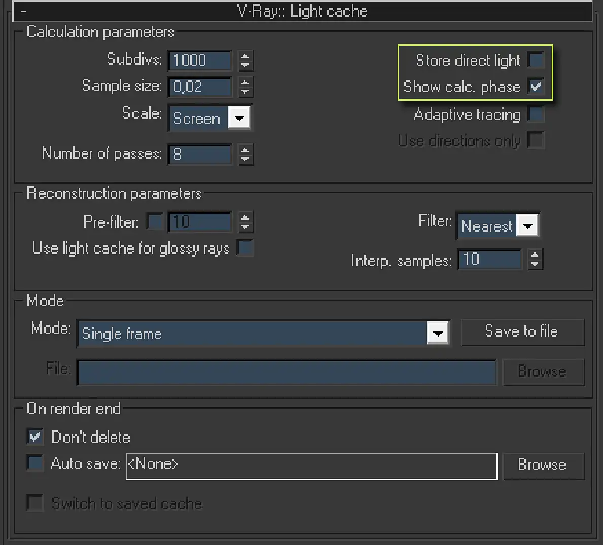
This screenshot shows the V-Ray:: Light cache rollout form the Indirect illumination tab of 3ds Max Renders Scene dialog. It contains such areas like Calculation Parameters, Reconstruction Parameters, Mode and On render end. The areas in turn contain parameters like Subdivs:, Sample size:, Scale:, Number of passes, Store direct light, Show calc. phase, Adaptive tracing, Pre-filter:, Use light cache for glossy rays, Filter:, Interp. samples:, Mode, Don't delete and Auto save:.
Subdivs: is a parameter that determines the number of LC rays, traced from the camera toward the scene to determine the samples color.
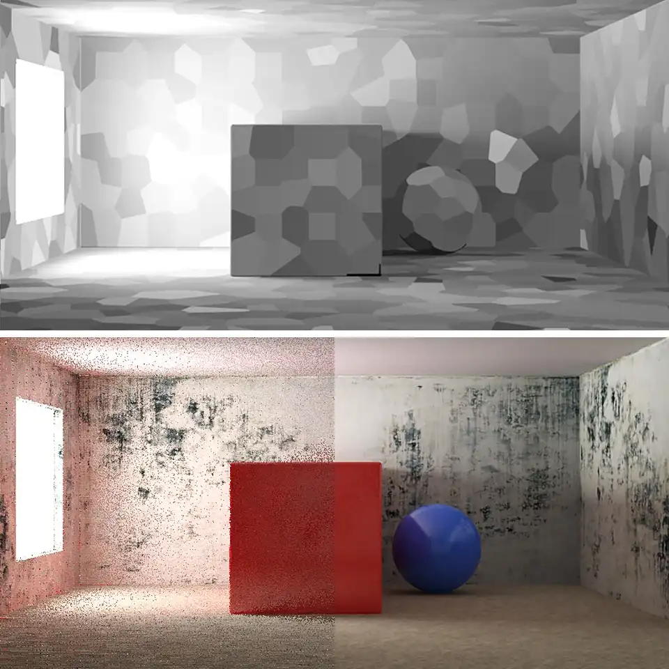
LC algorithm conventionally separates the scene into portions similar to mosaics cells. After that, it determines the color of each of them by sending there LC rays, traced from the camera. That is, each cell is an indivisible color sample that will be used in the resulting GI map.
Rendering of the example scene. It shows the mosaic cell of the Light cache samples.
Of course, the greater the number of rays determined by the parameter Subdivs:, the greater number of them will be "fired" to one cell and the more accurate will be determined each cell’s color. The actual number of LC rays equals to the square of the Subdivs: value, as well as for other functions using the identically named in V-Ray parameter.
Typically, the value 2000 – 3000 for Subdivs: is more than enough for the final rendering of photorealistic images. However, in the starting V-Ray configuration, the set 1000 Subdivs: value should be used and it can be raised only when this is necessary.
Sample size: determines the size of cell samples. When the cell size is specified, the LC algorithm divides whole image on them. After that, it traces rays to determine the color of each cell. To determine the color of the cell at least one ray is required. Let us assume that the total number of rays determined by Subdivs: is less than the total number of cells. Then the LC algorithm will be forced to paint some of the adjacent cells in one color, which visually looks like increasing the size of some cells. In other words, we can say that the visual size of the cells also indirectly dependent on the value of Subdivs:. The size specified by the Sample size: value will be achieved only if the scene will have sufficient number of LC rays. In the case if LC rays number is greater than the total number of cells, some cells will be calculated by several rays of the LC and will have more accurate color, which will improve the final rendering quality.
The cells size changing should be done only if the scene contains a large number of small details and LC map is insufficiently detailed for their correct representation. In most cases, nominally assigned a Sample size: value equal to 0.02 is sufficient for most scenes. That it should be used in the nominal configuration of V-Ray.
Scale: is a parameter in a form of drop-down list that allows us to specify the units of cell size. There are two values, Screen and the World.
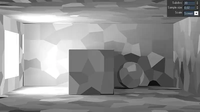
Screen allows us to specify the value of cell size in the fractional ratio of the final image. For example, if Sample size: is 0.02 and the Scale: is set to Screen, then it means that each cell will occupy 2% of the entire screen, etc. It should also be understood that the cell size, set relatively to the screen, does not depend on image size in pixels, and the geometry of the scene. That is, in a scene shown in the picture above, the cell size on the front face of the cube and on the wall behind him will be the same size, despite the fact that geometrically, these surfaces are at different distances from the camera.
The World value of Scale: parameter makes LC to use for defining the cell size the system 3ds Max units, set for this scene in the System Unit Setup. With this approach, cell sizes are geometrically identical, but visually their size relatively to camera depends on the geometry of the scene. In this case, in the scene shown on the image above, the sizes of cells on the wall behind the cube will be visually smaller than the size of cells on the front face of the cube. Also, considering that LC sampling every part of the image with fixed number of rays, the fewer LC rays get to smaller cells, compared with bigger cells. This will worsen the quality of the sampling of smaller cells. At the final rendering, it may appear as noise or artifacts in fine details of the scene.
The ability to set LC cell samples in system scene units created in order to obtain homogeneous LC maps for the further saving them to a hard drive and use in fly-through animations. This technique is applied in order to be able to render LC for the animation and have identical sizes of LC cells in all the frames, relatively to the scene geometry, regardless of the position of the camera.
For rendering the static scenes, as well as dynamic animations, when the LC map for each frame is calculated individually and cannot be used for the collection of frames, we must use the Screen mode. This will reduce the number of unwanted artifacts. That is the Screen value of Scale: parameter should be used for LC in universal V-Ray settings.
Number of passesis the number of passes of LC calculation. Nominally, calculation of LC is not a multi-threaded process; however, it can be intentionally divided into a number of passes (parts) to fully load all the threads of multi-core or multiprocessor systems. For example, if LC calculation is performed with the quad-core processor, we can to not break the LC on the passes, that is, set the Number of passes equal to unity. Then, during rendering of LC will be used only one core of a quad-core processor, and the remaining three will be idle, not participating in the calculation of LC. Therefore, to accelerate the LC rendering, it should be forcibly divided to the number of passes, a multiple number of available to system threads. As for today (Feb 2011), the number of cores in most available computer systems does not exceed eight. For example, eight cores available in a system with two quad-core Xeon processors in a dual processor motherboard. For most systems, a nominal set Number of passes value equal to 8 will be the best and that is what is used in the universal start V-Ray configuration.
Store direct light is a feature that allows the LC algorithm to save not only information about the GI, but also information about the direct light in the scene. As we know, LC traces rays from the camera to the scene objects. After crossing the ray with the object scene, the algorithm checks shader of object to determine its color, and continues to trace a ray from that point to the light source, illuminating this object, to determine the brightness. In other words, the LC algorithm in the performance of its working principle has to check also a direct the light that falls on calculation point. That is, it originally gathers information about direct light in the scene as well. Enabling Store direct light allows us to cache, i.e., save this information about direct light of the scene. Traditionally, after the rendering GI render element, V-Ray calculates separately the direct illumination of the scene. Sampling of scene direct light surely requires computational resources and takes time. Caching of light, i.e., previous storing information about it from the LC and the further use of readily available speeds up the final rendering, saving direct light calculation algorithm from the computational content. It is easy to imagine the quality of the thus obtained direct light. It will be much worse than the traditional sampling and will depend on the quality of the LC. This approach is justified only in very overloaded scenes with lots of light sources, where the direct calculation of the light takes many hours. Again, calculated this way images will have significant flaws, clearly betraying the computer-generated image origin. They will be dull with soapy and fuzzy shadows. In the photorealistic rendering, such an approach is not justified, even taking into account the substantial savings of computing resources. In nominal starting configuration of V-Ray, the feature Store direct light should be off.
Show calc. phase is an excellent, in some sense, an irreplaceable feature that lets us to display quite informative preview of the rendered image at the first minutes of the rendering. This eliminates the agonizing test renders at low resolutions and helps to easily adjust lighting and materials of the scene, without waiting for all stages of final rendering. Be sure to use it when setting up your scenes. Of course, this function should be used in universal V-Ray settings.
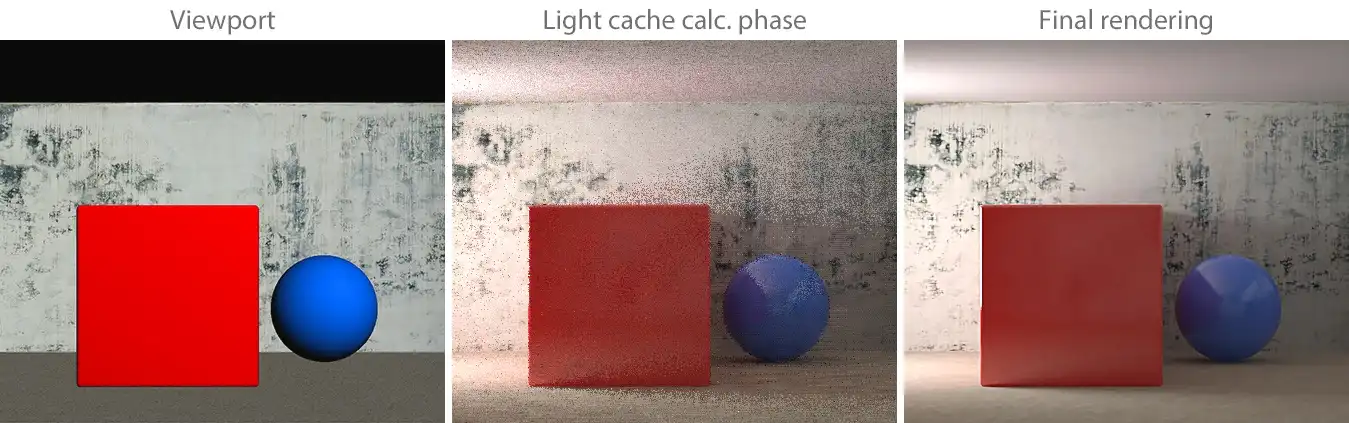
Three images for comparing. Left one is the viewport screenshot, which is rough and basically shaded. Middle one is the view of the LC calculation on the first minute of the rendering; it looks very close to the right one. Right image is the final rendering with highest quality.
Adaptive tracing is a feature that allows us to use additional information about lighting in the scene for each LC sample and add more rays in places with lots of light. In some cases, it helps to eliminate noise in the LC, for example, if a scene has caustics. However, it takes memory resources. On the Adaptive tracing parameter work also affects the function Use directions only, which is active only in the case when the first is enabled. In practice, these functions do not make a noticeable improvement in most scenes and in the starting V-Ray settings they should not be activated.
Light Cache Reconstruction Parameters
Next in the V-Ray:: Light cache rollout is the Reconstruction parameters area, which contains a few settings, responsible for post-processing of a calculated LC map, for using it in the final rendering images.
Pre-filter is a function that is responsible for interpolation of LC cell samples among themselves. Pre-filter interpolates the available LC sample map to obtain a more smooth result. Only then, it passes the map on to the final image rendering. The power of interpolation is determined by the numeric value next to the Pre-filter. Larger values give less noisy but more blurry results, what consistently leads to the disappearance of small parts and the appearance of "flying chairs". Small Pre-filter values give detailed LC map; however, due to weak smoothing of its samples, it can be very noisy.
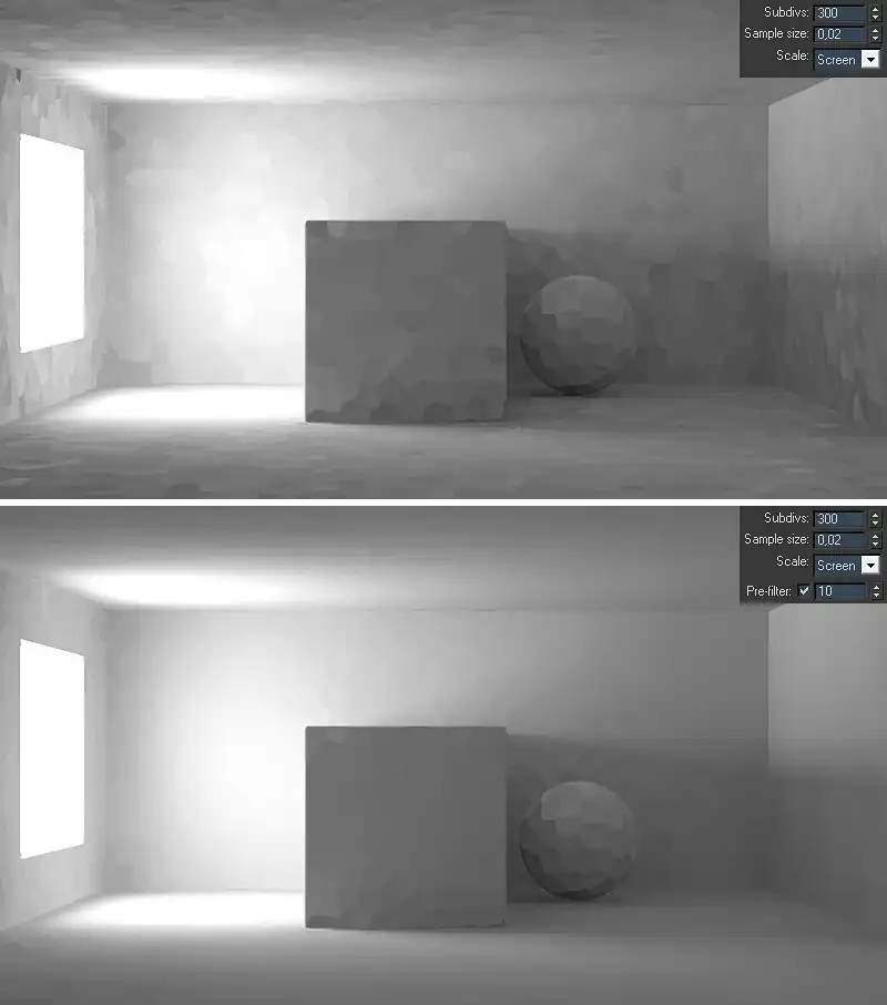
Two rendering of the example scene. They show the difference between using and not of the Pre-filter: algorithm. The second rendering with the Pre-filter: on looks smoother that the previous one, when no filtration was applied.
Filter is a drop-down list that allows us to select an additional interpolation algorithm of LC map in the final rendering. As mentioned earlier, V-Ray, after calculating the LC, passes the calculated LC map to the final rendering algorithm. Using the LC filter allows us to make an additional interpolation of LC on the final rendering stage. Once LC passed the map to the final rendering algorithm, the last begins the calculation of the shading points (the unit of rendering). If we select one of the filters (not to be confused with the Pre-filter), then when calculating each shading point, the final rendering algorithm will interpolate information from the LC sample map.
None is the Filter drop-down list item, which eliminates the use of LC filter. In this case, the final rendering algorithm will use the LC map as it is, without additional filtering.
Nearest is LC filter, used to interpolate a given point in the LC map with a certain number of nearby samples. Number of nearest samples involved in the filtration is determined by parameter Interpolation samples.
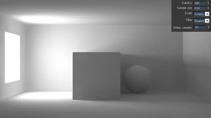
Rendering of the example scene with the enabled filtering Nearest. The image looks very smooth and have details.
Fixed is filter similar to Nearest, with the only difference that the number of samples involved in the modification of a given point on the GI map, is defined by a square area centered at this point. The size of this area is determined by the value of the Filter size: parameter. Units of Filter size: depend on the unit value of samples given by the parameter Scale: in the area of Calculation parameters, described earlier.
It is worth mention the fact that the filter Fixed calculates and modifies only the area that fall into a zone of Filter size. They look like squares with information about the scene secondary light, while other areas this filter leaves intact, which looks like a black background.
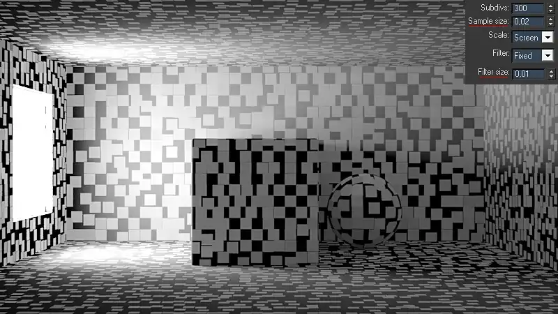
Rendering of the example scene with the Fixed Filter with the Filter size: smaller that the samples. It's like black geometry all covered with lots of gray sticky notes.
In order to avoid such significant artifacts on the LC map, we should always keep the size of these zones greater than the size of samples themselves, at least twice.
However, using a filter Fixed is justified only in the case of animation rendering and Sample size:, measured in system scene units, that is with Scale: set to Screen. In other cases, nominally it is worth using *Nearest *filter.
According to the work principles of the Pre-filter and Filter, it is clear that they in result perform the same function. They smooth (interpolate) the LC map, making it more uniform. These mechanisms differ only in the technical implementation. Pre-filter algorithm interpolates all samples at once for the entire LC map. However, its drawback is that it is single-threaded process, and regardless of the number of threads available to the system, it will use only one thread. At the same time, the Filter algorithm is calculated more accurately, because it occurs separately for each portion of the rendering. This approach requires more computational resources, making the V-Ray every time to calculate the interpolation for each portion of the rendering. Nevertheless, the process of Filter work, as well as final rendering, is multi-threaded and uses all available to system threads through which the computing load is distributed. For single and dual-core systems is rational the use of Pre-filter or a combination in the form of Pre-filter + Filter, where the number of samples interpolation is distributed to half or even with a great pass in to the pre-filtering. Most high-performance graphics workstations and even a gaming PCs are capable of treating four or more physical or virtual threads simultaneously. For them, it would be justified the using of the Filter algorithm. This rationality is particularly useful in distributed rendering, when in calculating a single image simultaneously multiple computers participate.
In the universal V-Ray settings, we should use only Filter: Nearest with the Interp. samples: set to 10. This algorithm and such degree of interpolation will give good not blurred detailed global illumination without evident artifacts.
Use light cache for glossy rays is an option, which lets to calculate diffuse reflections and refractions on the material objects in the scene, using the LC. It allows us to save computing resources. Is to be expected that the quality of calculated this way surfaces will be considerably lower than the direct calculation algorithm. The final rendering quality will depend on the quality and blur of LC map. As is in the case with a similar by goal Store direct light option, the information obtained when calculating the indirect illumination, also contains that information, which can be used in the calculation of diffuse reflections. Of course, the scene materials, calculated this way will look blurred and mess; that is just unacceptable for photorealistic rendering. Little influence on this situation can be achieved through a strong overstatement of LC settings to get relatively good Highlight glossiness and Refraction Glossiness in scene materials. However, then it will be a question of saving time and it will be especially important in distributive rendering. Unfortunately, at this moment in V-Ray, LC map cannot be calculated using the potential of the distributive rendering. Even in a network computing, the time of Light cache rendering will not differ from time of the rendering on a single computer.
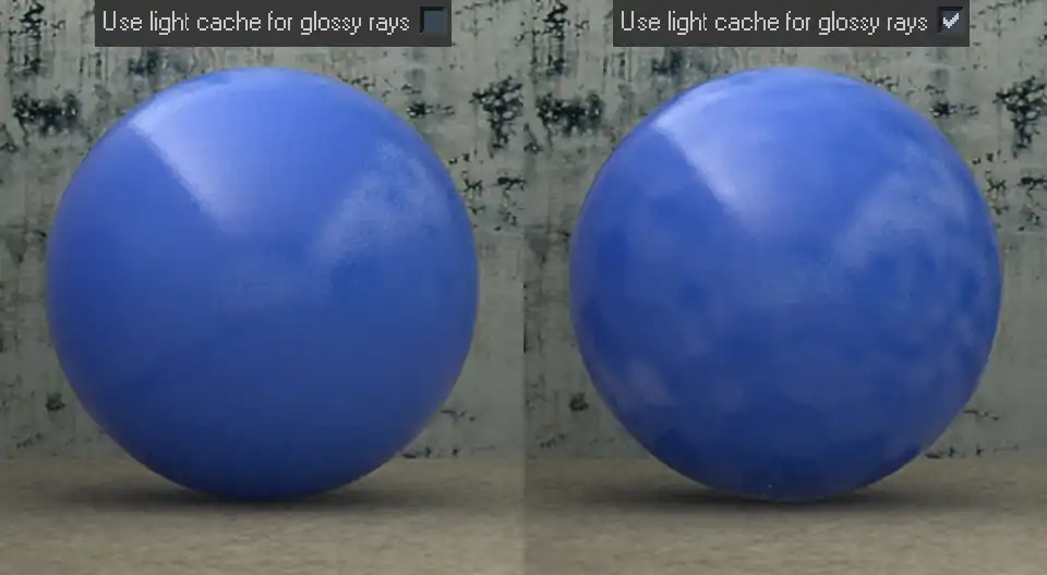
Rendering of the example scene sphere with the blue glossy material. It shows that the the using of the Use light cache for glossy rays function with the usual LC settings lead to very noisy look of the glossy reflections on the scene materials.
Therefore, in starting configuration of V-Ray, the option Use light cache for glossy rays should not be used, for a nominal exclusion of flaws and artifacts associated with its use.
The last two sections of LC settings are the Mode and On render end. They are similar to the same name sections, previously described in tutorial on Irradiance Map and will be studied in a separate tutorial dedicated to animation. In the universal starting V-Ray configuration it is worth keeping them as they are by default, they should not be changed.
Conclusion
In this tutorial, we met with two GI rendering algorithms, namely Photon map and Light cache and looked into the most important aspects of the last one’s work. In particular, we exhaustively learned all details, aspects and tweaks of GI rendering engine Light cache, and were able to see clearly everything on numerous examples.
Dear friends, we sincerely hope that after carefully reading this lesson, you are much closer to understanding the essence of the Photon map and Light cache. We also hope that you are now feeling free to use a lot of settings of the LC and are familiar with every function name. Understanding of this critical information allows easily configuring and getting of the great GI maps for photo-realistic 3d renderings.
See you in the next chapters of this tutorials series!
Share
Please share if you like it!