Indirect Illumination in V-Ray 1.5
The difference between direct and indirect illumination is explained. It will give you an understanding of global illumination nature and its role in computer graphics. It will show what is hemispherical diffuse reflection of light and the phenomenon of colored bleeding. What are primary and secondary bounces and why realistic 3D rendering requires special GI engines. How secondary lighting affects overall brightness of rendered images.
This series of tutorials was originally written in 2010. Then the working version of V-Ray was 1.5. The idea of this series is, firstly, to explain all the important concepts of visualization in simple language on illustrated examples, and secondly, to provide a package of initial values or so-called "universal" settings for the renderer which are tested in practice, suitable for most scenes and allow you to achieve best balance between quality and speed (rendering time).
Since then, in the latest versions of V-Ray (currently V-Ray 5), some settings have been renamed, moved to other sections, hidden or completely removed from the user interface.
To learn more, read the Main 2020 Update.
This is a tutorial series intended to guide you through all the basic V-Ray rendering settings. It successively describes all the V-Ray-related tabs located in Render Setup: ... (F10 key) dialog.
You can use the navigation menu below to learn more about other tabs settings from other chapters.
V-Raytab: Antialiasing & Color mapping in V-Ray 1.5Indirect illuminationtab: Indirect Illumination in V-Ray 1.5Indirect illuminationtab: Irradiance Map in V-Ray 1.5Indirect illuminationtab: Light Cache in V-Ray 1.5Indirect illuminationtab: Rationale for the Choice of GI Engines in V-Ray 1.5Settingstab: DMC Sampler or Speed vs Quality in V-Ray 1.5Settingstab: Ray Casting & Memory Allocation in V-Ray 1.5
Contents
Introduction
Hello everyone!
We are pleased to share with you a new portion of 3d stuff. We continue to discuss the best settings for V-Ray renderer, in this and the following three tutorials, we consider a second important part of any photorealistic 3D renderer - Indirect illumination. Before moving on to certain parameter values, it is extremely important to understand the concept of indirect illumination and its role in realistic 3d.
Global illumination is one of the modern rendering engine algorithms, which adds to the final image an additional render element. For ease of understanding of the rendering engine, the simplest way to imagine forming of final image is as it obtained by superimposing separate render elements, such as shadow, color, light, information about transparency, etc. each over other according to certain rules (blending modes). That is to imagine the final rendering as a collection of separate images with different information combined together. Those who know Photoshop can compare this process with the overlaying of different layers with a specific blending mode. Indirect illumination is one of the render elements, which adds to the overall result the information about the indirect light present in scene. To understand more exactly, what is added to the final image with this element, let us learn what the global, secondary or indirect illumination is in principle.
Indirect illumination in Nature
Indirect illumination is the illumination of the objects by the diffusely reflected light only, without direct light from the actual light source.
If you put some object in front of directional light source, such as window, and bring to the dark side of this object a sheet of white paper, you may notice that this dark side will be much lighter.
Bring closer and move away the white sheet from the unlighted side of the object several times, and you may see the difference in the final illumination of the surface with and without light sheet. The effect of lighting by a piece of paper would be even more obvious, if there are no objects around, which are as light-coloured as this paper sheet.
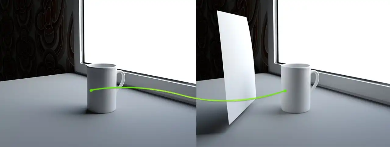
Demonstration of the diffuse reflection effect in nature. The not lit directly side of the object becomes lit if we bring the white material close to it. This is happening becuse of the indirect illumination or global illumination, how it is named in computer 3d graphics.
Why is this happening? Why does one object become brighter, if it appears beside the other bright object?
This happens because the effect called diffuse reflection. Bright object simply reflect rays falling on it from the light source. Therefore, reflecting, they illuminate the dark side of another object. Because of its origin, due to the fact that these rays are reflected and come from other objects, rather than going directly from the light source, they are called indirect. Accordingly, the light that is created by these rays, called indirect, that is, Indirect illumination.
It is easy to guess that ray, reflected first time from an object, also are reflected an enormous amount of times from other nearby objects. This avalanche-like process happens with all illuminated objects, eventually creating a set of reflected and mutually-reflected rays in all directions. Each subsequent reflected light ray carries less energy than previous ones because it is partially absorbed by the object from which the ray is reflected. Consequently, the light ray is fully faded. Due to the fact that this reflected light significantly illuminates even those sites that are not illuminated directly from a light source, that is, illuminating the global environment, this lighting part is called Global illumination or shortly GI.
To avoid further misunderstandings, "GI" is a very popular term in computer graphics. This is an abbreviation and literally stands for Global Illumination. It will be mentioned many times later, so you should know about it.
Global Illumination in Computer Graphics
Of course, all the photorealistic render engines are capable to simulate the global illumination, in some way calculating the first and subsequent reflections of light from objects in the scene, taking into account not only the color of these objects, but also features of their materials, such as transparency and reflective properties.
Let us see how indirect lighting looks like in computer graphics on concrete examples.
For this example we have created a simple scene in 3ds Max.
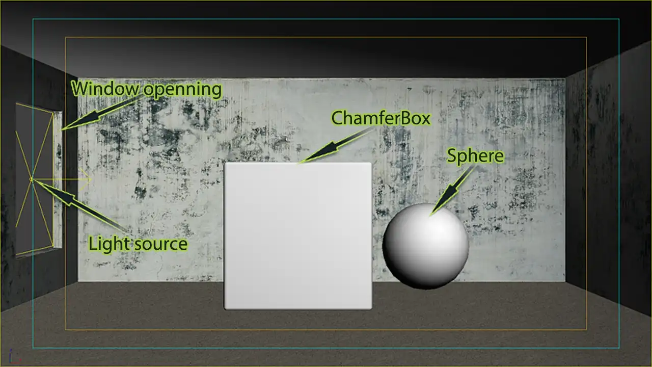
The structure of the example 3ds Max scene. It is the rectangular room with the square window opening, in which the VRayLight is set. Inside the room there are the ChamferBox and the Sphere. The walls have diffuse texture with other standard properties. The box and sphere have purely white color in the Diffuse color slot. This scene is created for representing the features of the Global illumination and its influence on the overall lighting on the 3d rendering.
The screenshot above shows that it is a rectangular room with a window opening into which the light source is set. Indoors near the window there is ChamferBox with little Fillet radius, and usual Sphere next to it. All materials in the scene are completely mat, without any reflections, even blurred. The materials of this scene have only the texture maps; the materials of cube and sphere are the standard materials with white color in the Diffuse slot.
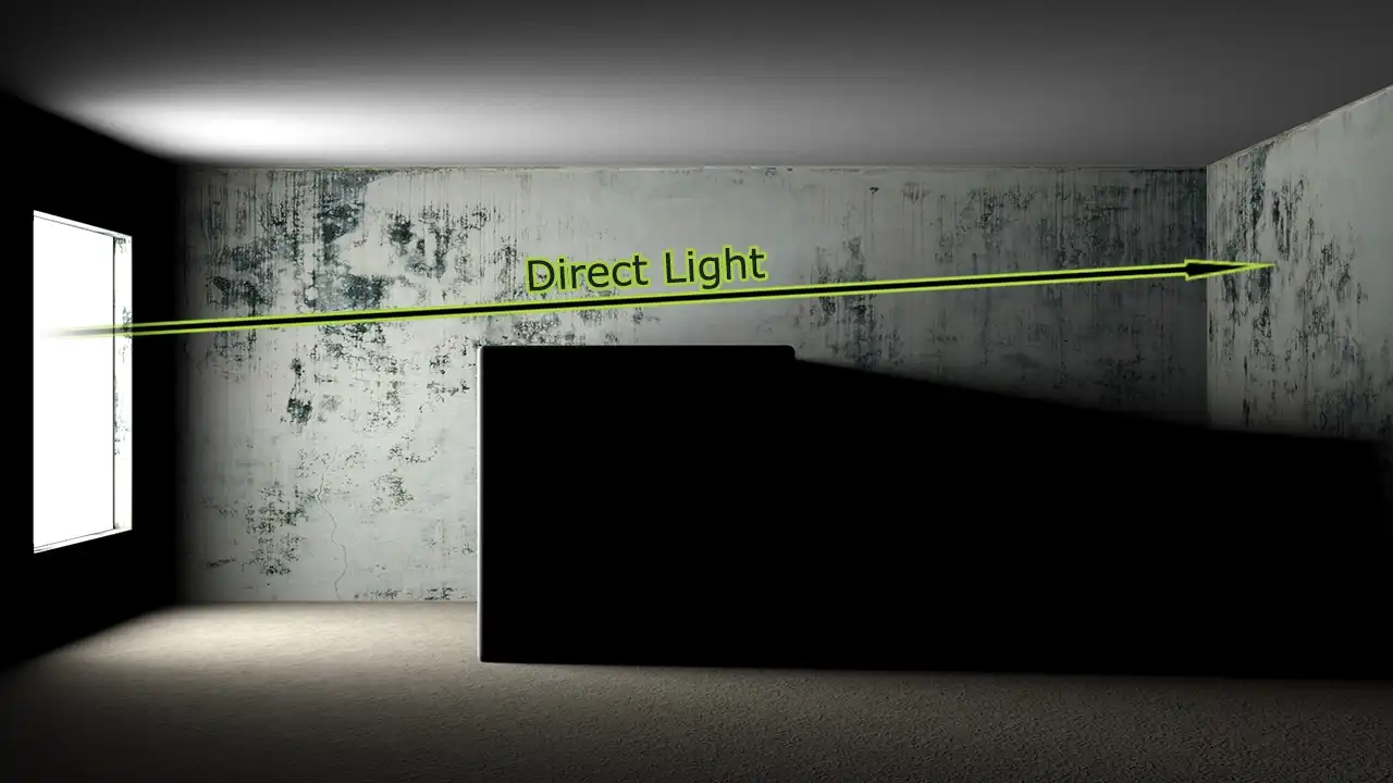
The rendering of the example scene with direct light computation only. The global illumination is not enabled here. Image shows the unnatural dark areas, which may appear in the areas that have no direct light falling on them. The absence of the diffuse inter-reflections leads to dark in not directly lit places.
This is the scene rendering. Note that only the direct rays from the light source illuminate it, without the use of GI. For clarity, one of the rays is shown schematically as a green arrow.
As can be seen on image, highlighted are only the areas of direct contact with the light rays. They are the floor and ceiling near the window opening, part of the wall near to the cube and the upper part of the wall opposite to the window opening where the arrow represents the light ray. Nevertheless, despite the presence of a bright source of light in the window and well-lit parts of the room, the scene still has a lot of unnatural dark areas. For example this is a wall with a window opening, visible to us the face of the cube, and the area right to it.
As seen from the screenshot of 3ds Max viewport, next to the cube is a completely white sphere. However, it absolutely is not visible.
Of course, in the real world, in such a situation it will be perfectly visible, even if it is not exposed to direct light rays.
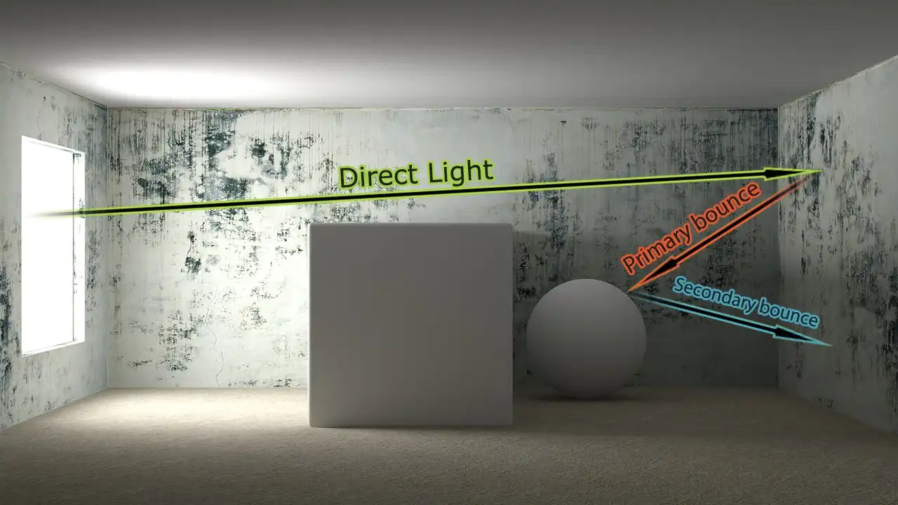
Realistic rendering of the example scene. Rendering was performed with the direct light and indirect light enabled. The previously dark areas became lightened because of global illumination, The arrows show the path of light travelling, The direct light shown in green strikes the opposite to window wall and lits it. Then, the reflected from the wall light lits the sphere that is not in reach of direct light. This is shown with the red arrow named Primary bounce. Then, light reflecting from the sphere and lits the bottom of the wall. This is shown in blue arrow called Secondary bounce.
This picture shows the same scene, same settings, the same source of light and materials, but it has a global illumination. You can clearly see that the scene is much brighter. A wall with a window opening has become lighter, as well as the visible face of the cube; in addition, now is clearly visible the white sphere, which on the previous rendering was in complete darkness.
To understand the effect of indirect lighting, look at the conventional Direct Light ray from the direct light source. As mentioned earlier, the indirect illumination is an effect of light rays reflection from all objects. The global illumination simulates exactly this effect in computer graphics. Ray of light comes from its source and hits the wall opposite to the window opening. Then, indirect illumination picks the baton so rays do not disappear, they are reflected, bouncing off the wall, falling onto the sphere. The red arrow conventionally represents it. Thus, the primary bounce happens from the scene object, and light falls on the sphere, of course, illuminating it. After that, the ray is reflected again, this time from the sphere and strikes the bottom of the wall behind it and, again, highlights it as well. This is shown schematically by blue arrow.
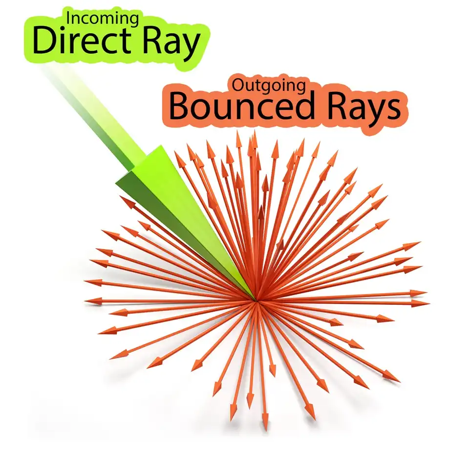
Number of secondary reflections of the ray is not limited to two bounces. They can be much more, depending on the settings the renderer. Also, it should be understood that each ray from the source of direct light upon reflection splits into many secondary rays of light. This amount also depends on the specific settings. In the above example the set of rays into which a ray of direct light breaks, not shown merely to simplify the scheme. More detail, the scheme of the diffuse reflection of the ray resembles turned over dandelion:
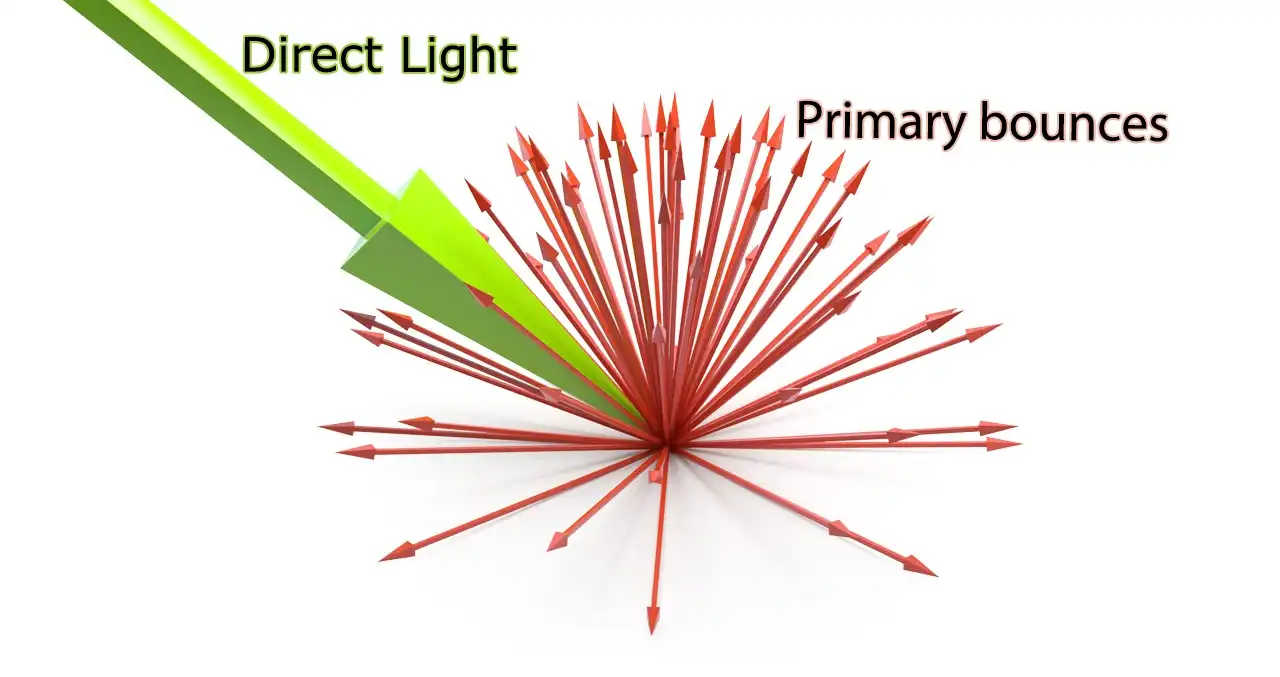
The scheme of the diffusely reflected light rays scattering. The green arrow represents original light ray, which after hitting the surface reflects in a number of bouncing rays. The directions of the reflection are disturbed in a from of dandelion, i.e., forming the hemisphere. The number of the rays in the hemishpere can be controlled by the special parameter in 3d computer graphics.
Original ray from the source of direct light, which shown with green color, hits the surface, then form secondary rays, shown in red. These secondary rays reflect from the surface diffusely, that is by scattering to the set of rays in all directions. In turn, these are already reflected rays, striking the other surfaces, in the same way, each again forms a set of rays, and so on and on. Global illumination ray can bounce many times, depending on the number of bounces, defined by the parameters of the renderer. Based on the image above, it is easy to imagine that they form a hemisphere, similar to a half of dandelion inflorescence. Vectors of the rays diverge in all 180 degrees in different directions, by the hemisphere from the point of reflection. That is how the rays behave in the GI engine, and because of the shape of the reflection, they are called Hemispheric Rays.
It should be noted that bounces of light rays of the global illumination in V-Ray is divided into Primary bounces (first reflection), and Secondary bounces (all subsequent ones). The first ray bounce from the object scene called the Primary bounce not without reason. The whole point is that the rendering engine that simulates the behavior of the real world sets the fading of the rays as they reflect. Therefore, as happens in the real world, the first bounce bears much of the reflected light energy. The energy of this first primary bounce is so significant that it much more than the light energy of all subsequent reflections together. It one affects the illumination of the scene greater than all subsequent ones. Conversely, in view of their lesser importance, all the bounces that follow the first primary one, called the secondary bounces.
Practical GI Setup
Well, it is time to figure out how to actually manage global illumination in the V-Ray.
Open the Render Scene dialog (F10 key) and go to the Indirect illumination tab.
In this tab, the general manager is the V-Ray:: Indirect Illumination (GI) rollout. It controls global illumination, rendering algorithms, the choice of primary and secondary bounces engines and general settings of GI.
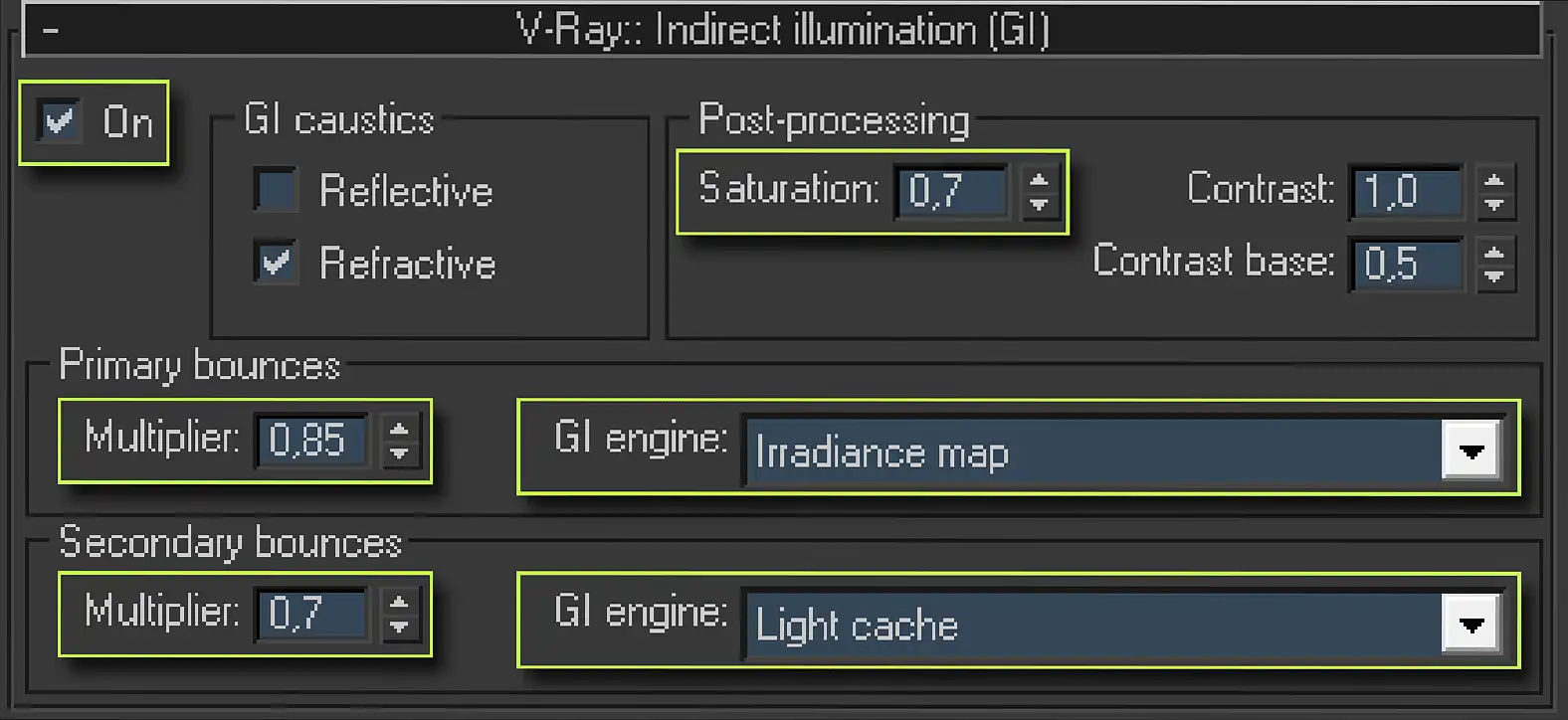
Screenshot of the V-Ray:: Indirect illumination (GI) rollout parameters, which is in the Indirect illumination tab of the Render Scene 3ds Max dialog. This rollout has On checked and divided into four zones: GI caustics, Post-processing and two similar zones, Primary bounces and Secondary bounces. They contain the following parameters: Reflective, Refractive, Saturation:, Contrast:, Contrast base:, Multipliers and GI engine:s drop-down lists.
First, to enable global illumination in a scene we should set tick in the checkbox named On. After this, we have available parameters of the V-Ray global illumination engine.
In first GI caustics area we can enable or disable the so-called Reflective and Refractive caustics for GI rays.
In short, caustic is the place where the reflected or refracted rays from the reflective and transparent curved surfaces are gathered, drawing a specific clearly visible light patterns. In other words, this is the effect of the curved lens, projecting the light rays on some surface, where the lenses are the reflective and transparent objects of the scene. The most obvious example of caustic is fancy light pattern on the table near the glass, on which the light shine from a side.
It is these effects simulates caustics photon map, situated in the V-Ray:: Caustics rollout. Despite the fact that current rollout is the last in the Indirect illumination tab and logical to write about it as the very last thing we would like to briefly write about it right now. The calculation of caustics in the V-Ray is accompanied by the appearance of a large number of artifacts, excessive consumption of memory and complex pre-configuration. All this is for the minimally noticeable, and often absent effect in most scenes. In the universal starting V-Ray configuration, rendering caustics should not be enabled.
However, it should be understood that the calculation of caustics and GI caustics are two different things. Caustics, created by the aforementioned photon map can be calculated only for direct rays of light. While GI caustics are calculated separately. The GI caustics configuration area in the V-Ray:: Indirect illumination (GI) rollout are responsible exactly for these caustics, which are originated from the global illumination. Moreover, GI caustics are called caustics only by a certain analogy with photon caustics, in fact, they are not.
Option Reflective allows us to enable rendering of reflective GI caustics for GI bounces, allowing GI-rays to take into account the reflective properties of materials and better reflect from reflective objects such as chrome, mirrors and other.
Given the lower energy of indirect bounced rays, compared with the rays from sources of direct light, the effect of reflective caustics on the overall scene illumination is negligible. In addition, since the need to render Reflective caustics by renderer, their inclusion will increase the render time of global illumination. Moreover, taking into account the complexity of this effect sampling, the appearing of unwanted noise in the GI is possible. Considering mentioned drawbacks, this option should be nominally left off in the universal starting V-Ray configuration.
Refractive option allows us to include rendering of refractive GI caustics for GI bounces. Despite the similar name to the caustic from the direct rays of light sources, where it simulated caustic lighting effects, Refractive caustics simply allows the passage of secondary illumination through the transparent surface. For example, this applies to the interior scene, which is illuminated by the indirect illumination from VRaySky / skylight / Skylight portal, located behind the window, and window openings are models of windows with glass. Lack of calculation of Refractive caustics in the scene will render all black, simply because the GI rays will not fall into the interior, because they not are able to pass even through the transparent glass window.
For most scenes, such behavior is unacceptable and therefore GI option Refractive in universal V-Ray settings should be activated by selecting the checkbox Refractive.
The next area of the V-Ray:: Indirect Illumination (GI) rollout is Post-processing, which contains three parameters.
Saturation is a very important parameter of GI, which is responsible for the color saturation of reflected light or, as practice shows, simply for the value of the so-called color bleeding effect.
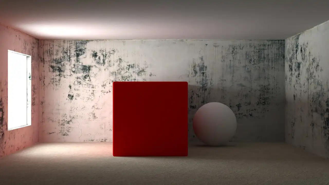
Rendering of the slightly modified example scene. All left unchanged but the material of the central cube. It is red now. Image represents the effect of color bleeding, which leads to lighting the all scene in the color of the inside objects. The scene is colored red because of the presence red cube in it.
This image is a rendering of used earlier scene, with the same light source, with the same material objects, with one exception, the material of the cube is red.
There is no need much time to look closely to the image, comparing it with previous ones to realize that not only the cube, but other scene objects got a reddish tinge. This effect is quite common for the real world, and actually is the phenomenon of color bleeding.
Its nature is quite simple. Red object is an object that absorbs the rays of all colors and reflects only the red color rays. It is this effect clearly imitated on this image. Direct rays of white color, which, as we know, bears all the colors of the visible spectrum, falling from a window on the surface of the cube, and then reflected. But they no longer reflected white, as they were originally. They are reflected red, as red material of a cube absorbed all the colors except red. Thus, the red cube lights nearby objects and paints them red.
Lowering a Saturation: value, will help to get rid of this effect. A lower value makes the color saturation of diffuse reflection paler, while the larger value makes it richer.
That is the same scene with the same red cube, but with a value of Saturation:, equal to zero:
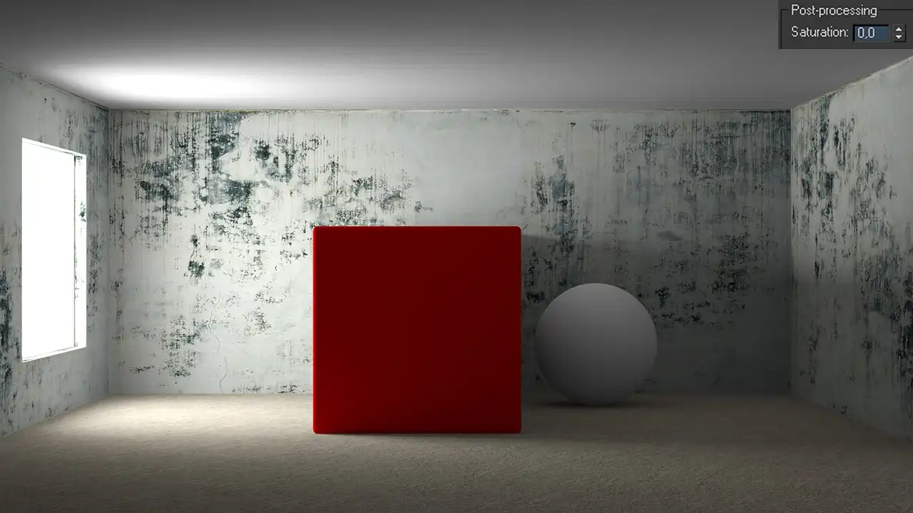
Rendering of the example scene with the red-colored cube inside it. The parameters of the rendering set so the Saturation: of the GI lighting set to zero. This means the diffuse GI reflection do not have any color contrast. Image shows there is no color bleeding effect at all even with the big red cube inside the room.
This image is no longer has red walls, but it should be understood that this is a global setting that affects every diffuse reflectance in the scene, reducing the color saturation of all GI rays. In most cases, a strong understating or overstating of this parameter gives an unnatural result. Optimal for the vast majority of the scenes is the value of this parameter equal to 0.7. That it must be set in the universal starting V-Ray configuration.
If there is a need to correct the effect of color bleeding of any particular object or material, for local control of this aspect the VRayOverrideMtl should be used.
Contrast: and Contrast base: are the parameters that literally control the contrast of GI, which renderer uses in forming of the final image, similar to how Saturation is essentially just controls color saturation of GI. Contrast: parameter works in conjunction with the Contrast base:. Technically Contrast base is one of the variables of the algorithm that computes the contrast of GI render element, shifting the range of its values, thereby affecting its brightness. When Contrast base is zero, increasing the value of the Contrast: parameter brightens GI; at the Contrast base greater than zero, the overall brightness is increasing, and increasing of the Contrast parameter value leads to darkening of GI.
In practice, these parameters are easily viewed as an analogue of Brightness/Contrast tool from raster editor - Photoshop. In the vast majority of cases, there is no need to somehow change the contrast of the GI. Therefore, in starting V-Ray settings, their value should not be changed, leaving 1 for Contrast: and 0,5 for Contrast base:, as it is set by default.
The next area of V-Ray:: Indirect Illumination (GI) rollout is a zone of GI engines choice of for Primary bounces and Secondary bounces of the light rays.
The number of GI settings causes panic to many 3d visualization artists. In fact, in these settings everything is fairly logical. There are primary and secondary bounces of the ray. Both are computed with special GI engine algorithms. There are four GI rendering algorithms in V-Ray. Their choice can be compared with choosing of antialiasing algorithms. There is one uncompromising calculation algorithm of GI bounces called Brute force and three slightly more flexible algorithms: Global photon map, Irradiance map and Light cache.
In areas of Primary bounces and Secondary bounces, there are only two parameters, a numerical Multiplier: parameter and GI engine dropdown list.
Multiplier: is a value of the current light bounce GI render-element applying intensity in formation of the final image. Simply it is its brightness.
By default, to Primary and Secondary bounces Multiplier values are set equal to unity. But this is not the most successful value, because of the excess brightness of the GI rays compared to the direct light rays. The images with these values are noticeably overbrighted and have no contrast. Often, it affects shadows much, which become lighter, so on rendering it immediately causes the effect of "flying" objects, under which the familiar shadows are absent.
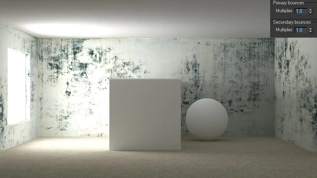
Example scene rendering with the default Multiplier: value for the indirect illumination, the Primary bounces and Secondary bounces. Image have the overall bright lighting what is quite unusual for real world. There is no correct balance between the brightness of the direct light and the reflected indirect.
Look closely at this image. It is quite bright, but all details of the scene are slightly visible, they appear blurred and fuzzy. This occurs because the indirect light lights the shadows, and thus greatly reduces the detail of the scene, making it flat. In scenes that contain objects of saturated colors, the value of Color bleeding is also increased, owing to the greater color influence of GI-rays on the scene. Also, it is not very clear what is the source of light in this scene, because there is absolutely no contrast between the bright light from the window and just as bright indirect lighting. There is an illusion that somewhere inside the room is an additional source of light. Nevertheless, very different picture can be observed on the image with a successful global illumination multiplier value.
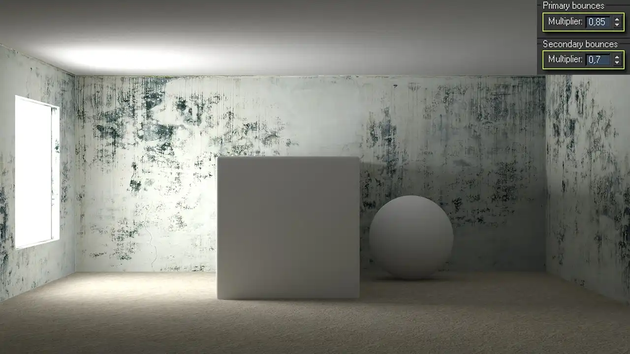
Rendering of the example scene with the correctly set Multiplier: values for the GI render-elements. The image is now looks natural, with the details. The correct light balance lets have the photorealistic brightnesses for the direct and indirect lights.
In this picture, the right balance between the intensity of the direct light from the light source and indirect lighting in a scene is chosen. Look at how clearly visible light background, there is no doubt that it is a source of light from the window, not the improvised indoor sources. There are also visible details much clearer; the scene becomes juicy and well worked out in detail. This approach significantly enhances the image contrast, making it more photorealistic. If the image seems not bright enough, this is elementary solved by raising the total Multiplier value in the V-Ray color mapping settings, located in the V-Ray: color mapping rollout of V-Ray tab in Render Scene window. More details about the global adjustment of final render brightness you can find in Replacement of VRayPhysicalCamera with Standard.
If you want only a minor refinement of overall rendering brightness, it is much smarter to alter it in 2d graphics editor. In addition, as mentioned in the first tutorial of the best V-Ray settings series, adaptive behavior of V-Ray render-engine is heavily dependent on the brightness of the image calculable. This means that calculation of the lighter GI inevitably lead to more time for rendering of the final image. For these reasons, we should choose the correct meaning of the brightness of GI. Rational and the most suitable for the vast majority of scenes and situations are the values of 0.85 for Primary bounces and 0.7 for Secondary bounces. These values should be used in the universal initial V-Ray configuration.
GI engine: are drop-down lists where we can choose one or another algorithm for rendering bouncing rays. In order to understand what algorithms should be used for Primary bounces and what for Secondary bounces, we need to become better acquainted with the each of them.
Conclusion
In this tutorial, we became more familiar with some important aspects of setting up the V-Ray renderer, in particular with the tools of V-Ray:: Indirect Illumination (GI) rollout, as well as with the theoretical basis of global illumination concept in CG and it nature in a real world.
Dear friends, we sincerely hope that after carefully reading this tutorial, you are much closer to understanding the essence of GI and the important role it plays in photorealistic computer graphics.
There will be more practice in the next tutorial. We will learn Brute Force and Irradiance Map GI engines and their practical application.
See you in the next chapters of this tutorials series!
We're glad you enjoyed this tutorial. The next tutorial of the series, which we will publish in just a few days, will answer this question in detail. However, if you want to know right now, Brute force as a Secondary bounces GI engine has a parameter called 'Secondary bounces' where you can set the desired number.
I believe that anyone, who interested in VRay settings, will probably be able to easily recreate this scene. It's just a simple box with a hole, like a 'window' with a random wall texture, and basic 3ds Max primitives, that is chamfer-box and a sphere. So there is no need to share this, you better test these settings on some real project that you have done recently to compare the results. It would be much more interesting and useful.
And say hello to Agent DanaScully!
If you are not an experienced V-Ray user, it is better to read all seven chapters of this tutorials series and only then draw conclusions about the final results. In any case, we will be happy to advise you as much as we can.
Thanks!
Share
Please share if you like it!